Maxwell's Equations - Gauss's Electric Field Law
Gauss's Electrical law defines the relation between charge ("Positive" & "Negative") and the electric field. The law was initially formulated by Carl Friedrich Gauss in 1835.
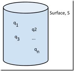
In Gauss's law, the electric field is the electrostatic field. The law shows how the electrostatic field behaves and varies depending on the charge distribution within it. More formally it relates the electric flux [the electric field flowing from positive to negative charges] passing through a closed surface to the charge contained within the surface.
The electric field flux passing through a closed surface is proportional to the charged contained within that surface
At this stage, if you have not read our Maxwell's Equations Introduction post; it is worth reading. The post is relatively short, but it does give an overview of Maxwell's Equations and puts them into context.
Gauss's Electric Field Law - Integral Form
In integral form, we write Gauss's Electric Field Law as:
 - integral Form
The first term tells us to take the surface integral of the dot product between electric vector (E in V/m) and a unit vector (n) normal to the surface. The dot product gives the electrical field normal to the surface and the integral the total electric flux ( ) passing through the surface.
The second term is the net charge (q in Coulombs) enclosed within the surface (divided by a constant of proportionality 1/ε0).
Together both these terms define the law in mathematical concepts.
By knowing an electric flux distribution through a surface, we can find the charge contained by the surface. Conversely knowing the charge contained within a surface, the electric flux passing through the surface can be determined.
Electric Field and Electric Flux
Electric fields are generated by charged particles (and varying magnetic fields). In a physical sense, it describes the force which would be exerted on a charged particle within the field. An electric field is a vector acting in the direction of any force on a charged particle. The magnitude of an electric field is expressed in newtons per coulomb, which is equivalent to volts per metre.
Electric fields are often represented by the concept of field lines. The lines are taken to travel from positive charge to negative charge. The stronger the electric field, the more lines are drawn to represent the field.
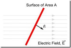
 Electric field passing a surface
 The concept of electric flux ( ) is the number of field lines going perpendicularly through a given area.
If all the electric field lines are perpendicular to the area, then the electric flux is simply given by the product of the magnitude of the field and the surface area:

Where the surface is not a right angles (see illustration), on the perpendicular surface to the field is taken into consideration in the calculation of the electrical flux. This as achieved by taking the dot product of the electric field vector and that of a unit vector perpendicular to the surface:

Where the surface is continually varying, the flux is calculated for each elemental area (da), and for the full surface is given by:

Note:
The SI Unit for electric field is V.m-1 [or kg.m.s-3.A-1 in base units]
The SI Unit for electric flux is V.m [or kg.m3.s-3.A-1 in base units]
Worked Examples
 Contained Discrete Charges
 To pull things together, we will work through two fairly simple examples. The first is that of enclosed charges and the second that of a parallel plate capacitor.
1 - Total Flux Through A Surface Surrounding Several Discrete Charges
The total flux ( ) is given by:

The total charge enclosed by the surface is:
 giving a total enclosed flux of
Consider five enclosed charges of 8, 4, -3, -4 and 6 nC respectively. The total electric flux through the surface is:

2. Calculate the Capacitance of a Parallel Plate Capacitor Using Gauss's Law
 Parallel Plate Capacitor
 A capacitor consists of two surfaces (one positively charged and one negatively charged). The ratio of charge on the plates to the voltage between the plates is a constant and is the capacitance:

Gauss's Law can be used to find the capacitance of any arrangement. For illustration consider the case of a parallel plate capacitor.
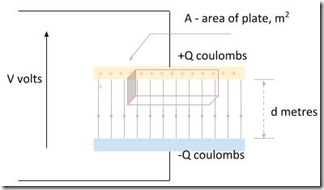
The illustration shows a parallel plate capacitor. Two plates of area A and separated by a distance d are charged (+Q on one plate and -Q on the other plate). This creates an electrical field between the plates.
Note: For calculation we assume a uniform electrical field. In reality, the electric field at the edges of the plates would not be a straight line but would slightly extend beyond the capacitor geometry.
Note: The net charge outside any capacitor is always zero.
To calculate the electric field flux we introduce a suitable Gaussian surface (a rectangular box in this case). The top of the box is within the capacitor plate and does not have any electric flux cutting it. The sides of the box are parallel to the electric field and hence no electric flux cuts these. Only the bottom of the box of is cut by the electric flux.
If we let the bottom area of the box equal the area of the plates, then from Gauss's Law (the right side) the total flux is:

For the parallel plate capacitor geometry, the left side of Gauss's Law resolves to:

The above two equations can then be combined to give the electric field (in V.m-1):

To find the total voltage across the capacitor, we simply integrate the electric field E between the plates:

Finally, arriving at the capacitance:

Gauss's Electric Field Law - Differential Form
In differential form, Gauss's Electric Field Law is represented as:

Whereas in the integral form we are looking the the electric flux through a surface, the differential form looks at the divergence of the electric field and free charge density at individual points. The left side of the equation describes the divergence of the electric field and the right side the charge density (divided by the permittivity of free space).
Electric fields diverge from positive charges and converge on negative charges. If the vector path of the electric field is known, we can use the equation to find the charge density (and vis versa).
To understand divergence of an electric field, it is useful to look at it's properties:
- divergence is positive when positive charges are present - the field tends to flow out from the charge
- divergence is negative when negative charges are present - the field tends to flow into the charge
- divergence is associated with points - to flow from or to the point depending on the charge
- divergence is none zero at points where charge is present
- divergence is zero at points where charge is not present
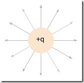
 Electric Field Around
A Point Charge Mathematically if the ratio of electric flux through a surface compared to the volume enclosed by the surface is taken, then as the volume tends towards zero, the ratio measures the divergence (the left side of Gauss's equation).
Note: the spreading out or condensing of electric field lines do not indicate divergence. We need to look at the flux entering and leaving an infinitesimal small volume. If these are the same, there is no divergence. If more flux leaves, there is positive divergence. If less flux leaves, there is negative divergence.
Consider the point charge shown. At the location of the charge (+q), no flux is entering and all the flux is leaving - this point has positive divergence. At all other points, the divergence is zero
Worked Example
To illustrate Gauss's Law in differential form, consider an electric field (in V.m-1) which oscillates along the x-axis according to:

Find the charge density associated with this field?


and substituting back into Gauss's equations gives:
 - charge density oscillates 90° out of phase with the electric field
Some Common Knowledge
To round this note off, here are a few extra bits to help with solving any problems involved Gauss's Electric Field Law.
Conductors - when a conductor is placed in an electric field, the charges are free to move to the polar regions. This creates an electric field within the conductor which cancels the effect of the electric field external to the conductor. Consequently, in electrostatic equilibrium, the electric field inside any conductor is equal to zero. Any residual net charge will always be distributed on the conductor surface.
Useful Equations - the table below lists a few of the more common and useful equations:
Summary
Gauss's Electric Field Law gives shows us the relationship between electric flux passing through a surface and the charge contained by that surface. That's the core of what most of us need to know.
To review all four of Maxwell's equations or investigate one of the other equations in depth, please see Maxwell's Equations – Introduction.