DC Motor Operation 

By on

Coils of wire on the rotor carry a d.c. current which generates a magnetic field. A stator magnetic field is created using either permanent magnets or electrical field windings.

Any current-carrying conductor placed within an external magnetic field experiences a force. Torque is produced in the motor by this mechanism.

As a d.c current provides a constant magnetic field, this needs to change each half revolution and is called commutation. Commutation is typically accomplished by metal brushes against the contacts. Where a field winding is used to generate the stator magnetic field, different motor characteristics can be obtained depending on how this winding is connected.

Operation Principals 

DC Motor Operation Principals
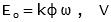
For the equivalent circuit the parameters are given by:


myElectrical EquationWhere:

myElectrical Equation       - lap winding

myElectrical Equation -       wave winding

given that

  • n = number of conductor
  • p = number of pole pairs
  • ω = motor speed, rad s-1
  • φ = flux per pole, Wb
  • T = torque Nm
and

myElectrical Equation

The power input to armature is given by:      myElectrical Equation

The armature power loss is given by:           myElectrical Equation

The output power is given by:                         myElectrical Equation

The torque is given by:                                     myElectrical Equation

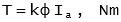
Typically, IaRa is ±3% of Va and the power dissipated in field winding ±3.5% of the motor rating.

Field Windings

Permanent magnets or field windings of a dc motor provide the necessary magnetic fields for the motor to operate(often call excitation):

  • permanent magnets - provides a continuous and constant magnetic field by the use of permanently magnetized materials (typically on only the smallest motors)
  • separately excited - separate windings and power supply provide the magnetic field for the motor
  • shunt winding - this is connected in parallel with the motor armature to provide the excitation
  • series winding - this is connected in series with the motor armature to provide the excitation
  • compound winding - is a hybrid between shunt and series where to field windings are connected both in parallel and in series with the armature

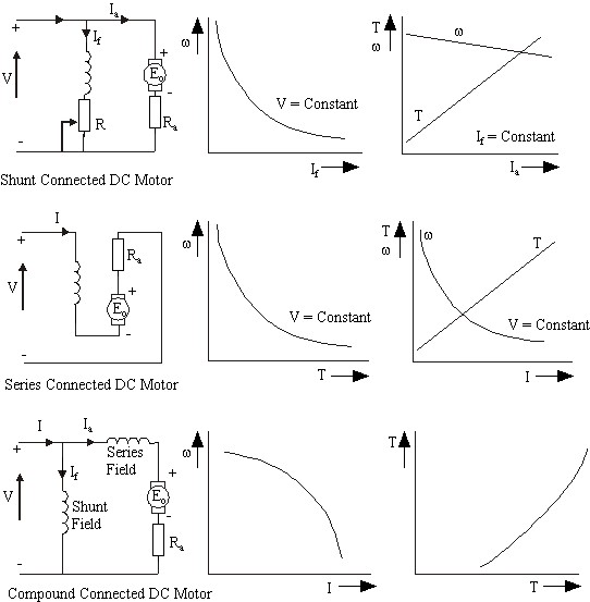
Characteristics of DC Motors


Speed Control of DC Motors

Separately excited, shunt

  • Constant power drive - Ia,Va is held constant and If varied
  • Constant torque If is held constant and Ia, Va varied

DC Converter output Voltages

Semi converter,       myElectrical Equation         
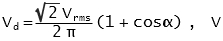
[DC converter equations do not look correct.  Please can someone check.]     

Full converter, myElectrical Equation - with infinite inductive filtering


Steven McFadyen's avatar Steven McFadyen

Steven has over twenty five years experience working on some of the largest construction projects. He has a deep technical understanding of electrical engineering and is keen to share this knowledge. About the author

myElectrical Engineering

comments powered by Disqus


Network Theory – Introduction and Review

In electrical engineering, Network Theory is the study of how to solve circuit problems. By analyzing circuits, the engineer looks to determine the various...

Write your best report

Years ago I was told that you should always try to write the best report you can.  Many years later I still think on this as one of the better pieces of...

What is Aircraft Ground Power

Ever wondered what kind of power an aircraft uses when parked at the airport stand. Normally the aircraft generates it own power, but when parked with...

What does N+1 mean?

The term 'N+1' relates to redundancy and simply means that if you required 'N' items of equipment for something to work, you would have one additional...

Electric Motors

Collection of links to various places with useful motor information. I’ll try and return to the page every now and again to update it with any motor notes...

RLC Circuit, Resistor Power Loss - some Modelica experiments

Modelica is an open source (free) software language for modelling complex systems. Having never used it before, I thought I would download a development...

Fault Calculation - Per Unit System

Per unit fault calculations is a method whereby system impedances and quantities are normalised across different voltage levels to a common base.  By removing...

How D.C. to A.C. Inverters Work

Traditionally generation of electricity has involved rotating machines to produce alternating sinusoidal voltage and current (a.c. systems). With the development...

8 Motor parts and common faults

Straight forward list of some common motor faults.  If I have missed any other common faults, please take a bit of time to add them in as a comment below...

Photovoltaic (PV) - Utility Power Grid Interface

Photovoltaic (PV) systems are typically more efficient when connected in parallel with a main power gird. During periods when the PV system generates energy...

Have some knowledge to share

If you have some expert knowledge or experience, why not consider sharing this with our community.  

By writing an electrical note, you will be educating our users and at the same time promoting your expertise within the engineering community.

To get started and understand our policy, you can read our How to Write an Electrical Note