Generation of a Sine Wave 

By on

A fundamental concept behind the operation of alternating current systems is that voltage and current waveforms will be sinusoidal – a Sine Wave. This is best explained by considering how a coil of wire behaves when rotated in a magnetic field.  

Faraday's Induction Law states that any change in the magnetic environment of a wire will cause a voltage to be "induced" in the wire. This can be expressed mathematically as:

myElectrical Equation

where:

V - induced voltage, V (volts)

B - magnetic flux density, T (tesla)

l - length of conductor, m (metre)

v - velocity between conductor and magnetic field m.s-1 (metre per second)

θ - angle between conductor and magnetic field, radians (or degrees)

If the wire is moved parallel to the magnetic field, the resulting angle is zero and the induced voltage with be zero. If the wire is moved perpendicular to the magnetic field (sin θ = 1) then the maximum voltage will be induced (for a given field and velocity). At any other angle the voltage will be proportional to the sine of the angle.

Generation of Voltage
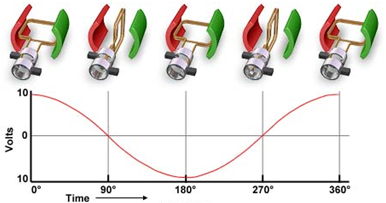
Sine Wave GenerationIn practice voltage is generated by rotating a coil of wire through a magnetic field in a generator. The illustration shows this process. Initially the coil is perpendicular to the magnetic field generating maximum voltage. As the coil rotates the voltage decreases according to the sine of the angle until the conductor is parallel to the magnetic field. Further rotation then increases the voltage until once again it is at a maximum (but in the opposite direction).

For each revolution a complete sine wave is generated. The number of sine wave cycles generated per second (the frequency) depends on how quickly the generator is rotating.

In practice each generator coil will have several turns of wire. For 'n' turns, the total voltage will be 'n' times that given by the above equation. Real generator winding are often more complex than that of a single coil, however the basic goal of constructing machines to generate a sine wave still apply.


Steven McFadyen's avatar Steven McFadyen

Steven has over twenty five years experience working on some of the largest construction projects. He has a deep technical understanding of electrical engineering and is keen to share this knowledge. About the author

myElectrical Engineering

comments powered by Disqus

  1. drdimitri's avatar drdimitri says:
    11/19/2012 10:00 PM

    Actually, in practice the wires will be embedded in a ferromagnetic rotor, thus the voltage produced will be a square-wave and not sinusoidal. Also, in practice the rotor will be the magnet and the stator will have the windings (synchronous machine).

    • Steven's avatar Steven says:
      11/20/2012 12:26 PM

      Thanks for the comments drdimitri. They bring out a valid point.

      The theory described above is correct and useful in explaining how a sinusoidal emf is generated, which was the intent of the page. As an additional reference, readers can refer to Hughes, Electrical Technology Seven Edition, page 192, which describes much the same analysis.

      You are correct that practical machines are more complicated than the simple coil type shown and that the magnetic flux does not behave the same. The high reluctance of the air gap (compared to the rotor and stator) forces the magnetic flux to be perpendicular between the rotor and stator. To obtain a sine wave the turns are distributed in closely spaced slots around the rotor and varied in a sinusoidal manor.

    • drdimitri's avatar drdimitri says:
      11/20/2012 12:45 PM

      Exactly! This is one of the questions I always ask my students and at first they always forget that the air gap introduces a very high reluctance, so they think that "by default" a generator will produce a pure sine wave. It actually takes a lot of effort to produce a sine wave, as you have pointed out (distributed windings)...


Comments are closed for this post:
  • have a question or need help, please use our Questions Section
  • spotted an error or have additional info that you think should be in this post, feel free to Contact Us


DC Component of Asymmetrical Faults

The image (reproduced from IEC 60909) shows a typical fault in an ac system.  From the illustration it can seen that there is an initial dc component ...

Resistors

Resistors are electronic components that oppose the flow of current.  Manufactured in various types and ranges they have a wide application to electronics...

Why is electricity so hard to understand?

It's been a busy few months on different projects or busy couple of decades depending on how I look at it. I can say that on the odd (frequent) occasion...

3 Phase Loads

Three phase systems are derived from three separate windings, either connected in delta or star (wye). Each winding can be treated separately, leading...

How to Write an Electrical Note

Electrical notes are a collaborative collection of electrical engineering information and educational material. Any registered user can add content. ...

Fault Calculations - Typical Equipment Parameters

A frequent problem in fault calculations is the obtaining of equipment parameters.  While it is always preferable to use the actual parameters of the equipment...

What is LED?

Light Emitting Diodes (LED ) are increasing gaining favour in both the domestic and commercial sectors; due to their efficiency, sustainability and durability...

MIT OpenCourseWare

MIT OpenCourseWare, makes the materials used in teaching all MIT subjects available on the Web, free of charge, to any user in the world.

Surface Treatment – Ladders, Trays and Baskets

Steel ladders, trays and baskets form the backbone of cable containment systems. Often these items need some form of surface treatment to prevent corrosion...

Bows and Arrows

It starts with me reading one of the Horrible History books with my son (Groovy Greeks). Arrows were mentioned which lead to the discussion of the bodkin...

Have some knowledge to share

If you have some expert knowledge or experience, why not consider sharing this with our community.  

By writing an electrical note, you will be educating our users and at the same time promoting your expertise within the engineering community.

To get started and understand our policy, you can read our How to Write an Electrical Note