Lighting Design - An Introduction
From the earliest times, humans have found ways to create light. Pre-historic peoples used natural materials (moss, grass, etc.) soaked in animal fat and then ignited. Around 3000 to 4500 BC, oil lamps and then candles were invented. During the 18th and early 19th centuries, the technology of oil lamps improved and gas lighting was developed. Starting in the middle of the 19th century, electrical lighting became available with the invention of the fluorescent and incandescent lamps.
Technology has continued to improve and today we see the massive use of electrical lighting in the form of fluorescent, mercury and sodium vapor, metal halide and light emitting diodes (LED). Technology is continuing to develop with the latest developments being the introduction of magnetic induction and sulfur lamps.
Lighting design is the field of creating light, its application and use by people. Lighting design starts by developing the objectives and then quantifying these by specifying the criteria. When looking objectives, the lighting designer will consider:
- day lighting and how it is used
- types of artificial lighting to be considered
- required light levels and uniformity
- types and methods of lighting control
- maintenance of the slighting system
- the efficiency goals of the lighting system
Lighting Levels
A key consideration of the lighting design is the selection of illuminance values and required uniformity. Typically reference is made to tables in local design guides. Values given in the table are not mandatory and individual considerations may give need to adjust these values.
Lighting Software
| During recent years, the use of lighting design software has become standard practice. Most software involves modelling a physical representation of the area to be lit, selecting the fittings and looking at the light distribution. Software will contain luminaire data from a variety of manufacturers. Where particular manufacturers luminaires are missing from the software, data files for these can generally be downloaded from the luminaire manufacturers website and imported into the lighting software. Links to come free and paid for lighting software can be found at: | 
AGi32 rendering of lounge at
Canberra Airport |
Lumen Method
Prior to the use of lighting software, the Lumen method, was commonly used to calculate the required number of fitting for rectangular arrays. In the method the average Illuminance E(s) over a reference surface s is given by:
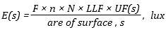
where:
- F - is the initial lamp lumen, lm
- n - is the number of lamps per Luminaire
- N - is the number of luminaires
- LLF - is the light loss factor
- UF(s) - is the utilisation factor for the reference surface, s
F is the initial lamp lumens. Light output reduction during the lamp life being included in the light loss factor.
 UF(s) measures of the efficiency of the lighting scheme considering light on the working plane to consist of direct light and reflected light. While it can be calculated, UF(s) is more commonly looked up from manufacturers tables. Tables will list UF(s) for differing wall, ceiling cavity and floor cavity reflectance's and the room index. The room index RI, is dependant on the room geometry and given by:
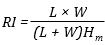
Note: for different shapes, RI is calculated by dividing the room into two or more rectangular sections.
When using manufacturers tables with the Lumen method, utilisation factor tables, typically include maximum Spacing to Height Ratio (SHR) for the luminaire. Adhering to SHR ratios, will ensure some level of uniformity of the Illuminance.
Glare
Excessive contracts in illuminance can result in glare, resulting in discomfort is a reduction in the ability to see or perform a task. There are a variety of ways to calculate glare – common ones being the Unified Glare Rating (UGR) for interiors, Glare Rating (GR) for outdoor areas and sports venues and the Threshold Increment (TI) for street lighting.
As with illuminance values, recommended glare ratings can be found in tables in local design guides. Depending on area values for UGR typically range from 16 to 28, GR from 45 to 70 and TI from 10 to 15.