How D.C. to A.C. Inverters Work
Traditionally generation of electricity has involved rotating machines to produce alternating sinusoidal voltage and current (a.c. systems). With the development of power electronics during the last several decades, semi-conductor devices are now frequently used to convert direct current (d.c.) to a.c. to power conventional alternating current systems.
Devices used to convert d.c. to a.c. are called inverters. These are used numerous applications, including PV systems, battery storage systems, traction drives, variable speed drives and others. While they are said to convert d.c. to a.c., this is a simplification, and as we will see, the output of any inverter is built up by pulsed d.c. voltages.
If you are not familiar with sinusoidal a.c. voltage and current, you can refer to the following notes for some revision:
Type of Inverter
Converting a d.c. voltage to a sine wave is not a straight forward process. The general approach is to chop (pulse) the d.c. voltage so that it approximately resembles a sine wave. This waveform can then be filtered to bring it closer to that of a sine wave. The level (and associated costliness) to which these techniques are applied determine the final quality of any sine wave produced.
When considering inverters, the quality of their output is often classified into general categories:
- Square Wave Inverter
- Modified Sine Wave Inverter
- Pure Sine Wave Inverter
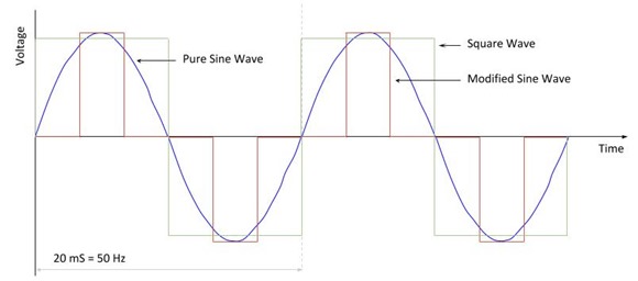
 Comparison of various waveform types
 A square wave is very simple, with the d.c. supply switched between positive and negative. Depending on the circuitry, the simple square wave can be adapted to give a modified sine wave as shown. By utilising Pulse Width Modulation (see below) and filtering techniques, the waveform can be refined until it closely resemble that of a pure sine wave.
There is no exact cut off which defines a pure sine wave and various manufacturers will have differing specifications. It is generally argued that when the total harmonic distortion of the voltage waveform is less than 3%, for all practical purposes this can be considered as a true sine wave.
A lot of equipment will work well on modified sine wave inverters, including motors, household appliances and other items. Some types of loads they can be problematic and do require a pure sine wave converter. A well know example are loads requiring a pure sine wave are devices that include crystal oscillator electronic timing circuits which rely on a zero crossover of the sine wave for the functioning.
Pure sine wave inverters are more complex and cost more. It is best to select the type of inverter to match the application for which it will be used.
Pulse Width Modulation
Most inverters use a technique called Pulse Width Modulation (PWM) to turn the d.c. voltage on and off. The width of each pulse is varied, so that the overall electrical effect is similar to that of a sine wave. This technique is often applied when powering a..c motors. For a more detailed explanation of how PWM works, please see our Variable Frequency Drive note).
_thumb.jpg) Pulse Width Modulation - the width of pulses is varied to simulate a sine wave
Pulse Width Modulation - the width of pulses is varied to simulate a sine wave
Pulse Width Modulation - the width of pulses is varied to simulate a sine wave
It should be understood that the output of this type of inverter is not a pure sine wave. It is a series of d.c. pulses. This can make it unsuitable for certain types of equipment.
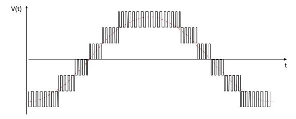
The diagram below illustrates a PWM waveform for a standard inverter - where a single d.c. voltage is with switched on or of to generate the required output. In this instance, more input d.c. voltage levels are used to create an output waveform which more closely resembles a sine wave. Multilevel type inventors are more complex and costly to produce.
 Multi-level (3 levels) Wave Form
Harmonics - with the PWM waveforms not being sinusoidal, harmonics will be generated. For multilevel inverters, the more levels employed, the closer the output will approximate a sine wave and the harmonic content will be lower.
Inverters frequently employ the use of transformers, capacitors and inductors to filter the PWM waveform and reduce the harmonic content.
H-Bridge Circuit
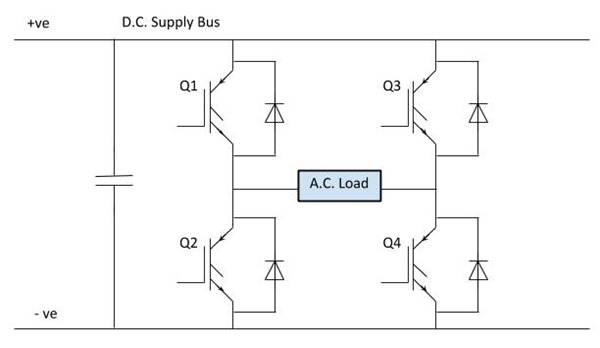
At its simplest, an inverter consists of what is known as a H-Bridge arrangement. The circuit below illustrates the implementation of a single phase H-Bridge circuit using Insulated Gate Bipolar Transistors (IGBT).
 H-Bridge using IGBT
 The operation of the bridge is straight forward. The IGBT act as a switch (when a signal is applied to the gate, they turn on and then turn off when the signal is removed). By closing Q1 and Q4, a positive d.c. supply is applied to the load. Q2 and Q3 will result in a negative d.c. supply across the load. Control circuits are used to generate the necessary gate signals to produce the required PWM waveform.
To avoid short circuits (closing both Q1 and Q2 at the same time for example); when changing polarity it is necessary to turn off one set of IGBT before turning on the next. During the transition, all the IGBT on off. Diodes provide a necessary path for inductive current in order to limit potential voltage build up during the transition period.
The capacitor provides smoothing to even out any variation in the d.c. supply.
By utilising six IGBT, it is possible to use the bridge arrangement to supply three phase loads.
H-Bridge arraignments are also commonly implemented using Bipolar Junction Transistors ((BJT) or Metal Oxide Semiconductor Field Effect Transistors (MOSFET)
Putting it together
_thumb.jpg) Inverter Block Diagram
Inverter Block Diagram The block diagram illustrates the key components of a d.c. to a.c. inverter.
- Input Filter - the input filter removes any ripple or frequency disturbances on the d.c. supply, to provide a clean voltage to the inverter circuit.
- Inverter - this is the main power circuit. It is here that the d.c. is converted into a multilevel PWM waveform.
- Output Filter - the output filter removes the high frequency components of the PWM wave, to produce a near sinusoidal output.
Note: if you are familiar with Fourier Analysis, it will be seen that the periodic PWM waveform consists of a main fundamental frequency component and higher order (but lower magnitude) harmonic components. It is these higher order harmonics which the output filter is eliminating.
Inverters are complex devices, but they are able to convert d.c. to a.c. for general power supply use. With advances in power electronics and microprocessors, the application of inverters in many fields is increasing. Overall, inverters allow us to tap into the simplicity of d.c. systems and utilise equipment designed these to work in a conventional a.c environment.