Star-Delta Motor Starting - Performance
Many questions sent in to the site are in connection with motor starting and in particular star-delta. For all but the simplest application, there is merit in performing a more detailed study. Carrying out a software study allows both the electrical performance and that of the connected mechanical systems to be evaluated.
This note illustrates by example one possible approach to studying the performance of a star-delta motor starting circuit.
The Example
A relative simple example of a 15 kW motor supplied directly from a source and with the load modelled by a simple inertia will be investigated. It will be easier to examine and understand the principles by keeping the model simple.
The technical parameters of the model are:
- 15 kW, 380 V, 50 Hz, 1 pole pair squirrel cage motor
- stator resistance, Rs = 0.0258 pu and reactance Ls = 0.0930 pu
- rotor resistance, Rr' = 0.0145 pu and reactance Lr' = 0.0424 pu (referred to stator)
- magnetising inductance, Lm = 1.7562 pu
- stator zero sequence inductance Lo = 0.930 pu
- connected inertia = 0.15 kg.m2
To illustrate and understand the performance of the motor starter, modelling is carried out in three stages:
- creating a direct-on-line starting model
- modifying (1) to model an star-delta open-transition starter
- modifying (2) to model a star-delta closed transition starter
Motor Starting Circuits
_3.jpg) In writing the post, it is assumed that the reader has some understanding of motor starting circuits. If you are unfamiliar with these types of circuit, you can refer to a short introductory eBook on the topic - "Motor Starting and Control Primer."
In writing the post, it is assumed that the reader has some understanding of motor starting circuits. If you are unfamiliar with these types of circuit, you can refer to a short introductory eBook on the topic - "Motor Starting and Control Primer."
By first constructing a direct-on-line model, we can verify the output is in-line with expectations and that the model is functioning correctly. The direct-on-line model output also give us a base-line performance against which to compare the results of star-delta starting.
Models for star-delta starting will cover the two common implementations of open-transition and closed-transition. In open transition, there is a break in power while switching between star and delta, whereas in closed transition resistors are employed to eliminate any power break.
Practical implementation of star-delta starters typically use timer relays to control the switchover. The model examples use timing signals to mimic this behaviour. When to change from start to delta is often quoted as being the time when the motor has run up to 75 to 85% of it's operating speed. To investigate this rule, we will look at three scenarios with changeovers occurring at 70%, 80% and 90% of full speed.
Note: from a modelling perspective it may have been easier to use actual speed signals to control the change over. However, utilising timing signals and setting these individually may make the model logic easier to follow.
Circuit Modelling
Models were developed using Simulink and the post gives only brief explanations of how they function. For more detailed information on any aspect, you can visit the Simulink website.
Using the models, we can measure and analysis numerous parameters. Of these, the three which are of most interest to engineers (and often the subject of text book consideration) have been chosen for consideration:
- stator current
- electrical torque
- speed
Direct-On-Line Starting
Direct-on-line starting is straightforward. A line contactor closes to connect the supply directly to the motor. The motor windings are connected in a delta configuration.
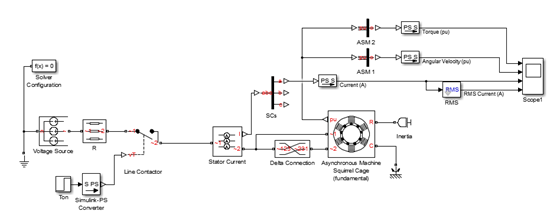 Direct-On-Line Circuit Model
 The illustration (click for a larger image) shows the circuit used to model the behaviour of direct-on-line starting. Although the model is fairly straight forward, I'll briefly explain the function of each element:
- asynchronous machine squirrel cage - models the dynamic behaviour of our motor (using a Park's dq0 transformation)
- a three phase voltage source supplies power to the circuit and resistance, R = 0.5 Ω simulates the source impedance and transmission path
- a switch (line contactor) operates after 0.4 s (set by Ton) to connect the supply to the motor
- the thee phases are directly connect to the positive end of the windings (~1)
- phases are also transposed in the 'Delta Connection' and connected to the negative end of the windings (~2)
- connected inertia is represented by the 'Inertia' element
- the 'Stator Current' sensor and (pu) terminals allow measurements to be taken and displayed by the scope block
The plot below shows the results of running the simulation.
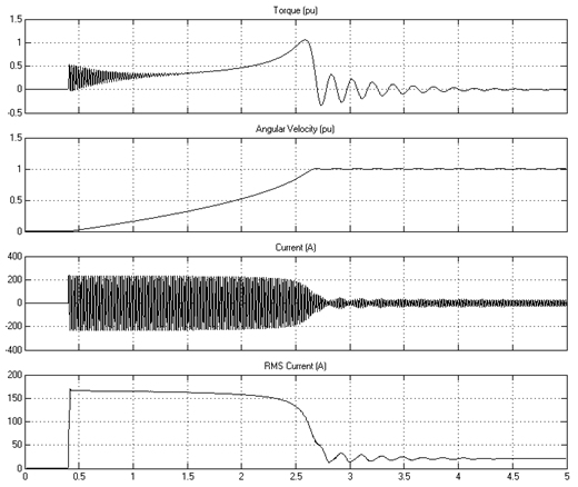 Direct-On-Line Results
 The results show what would be expect of a direct-on-line starter from fundament theory. Speed gradually increases to full speed and the electrical torque follows the anticipated profile and increasing and then dropping once the motor is up to speed. The motor current starts high and then drops off to the normal running value as the motor reaches full speed.
Note: for anyone interested in the electrical theory, more details are given in our Induction Motor Equivalent Circuit note.
Speed and torque are plotted in per unit (pu). For the current, real values are plotted as these are of most interest to any engineer implementing starting circuit. In addition, both the instantaneous and rms curves for current are plotted.
By inspecting the results, the important conclusions are:
- time to full speed is around 2.7 seconds
- full load current is approximately 166 A
- starting current is approximately 21 A (7.9 times the running current)
Timing (motor connected in star)
Before moving on to consider star-delta starting, the direct-on-line model is run with the motor winding in a star configuration. The image shows that this is achieved by connecting the negative windings (~2) to earth. The aim of this is to obtain timing points for the star delta transitions.
_thumb.png) Creating a Star Winding
Creating a Star Winding The output (not shown) follows that of the delta connected scenario, but the starting currents are less (and consequently torque) and the acceleration times longer.
By investigating the speed plot, we find the durations (starting from t=0) at which the motor has accelerated up to the switching points of interest to us.
- 70% of full speed at 3.13 seconds
- 80% of full speed at 3.36 seconds
- 90% of full speed at 3.48 seconds
Star-Delta Open Transition
In a star-delta open transition starter, the power is first supplied to the winding in a star configuration. After the appropriate time delay, the power is disconnected, windings reconfigured to delta and the power reconnected. The time delay between disconnecting the motor in star and reconnecting in delta is typically around 40 mS.
Utilising the results from the direct-on-line study (star connected winding), the timing events for our 70% star-delta design can be described as:
- Ton at 0.4 s - power connected, star contactor closed, delta contactor open
- Ts at 3.53 s (3.13 + 0.4) - star contactor opened
- Td at 3.57 s (3.53 + 0.04) - delta contact closed
For short hand, the three scenarios to be considered can be expressed as:
- 70% - 0.4, 3.53, 3.57
- 80% - 0.4, 3.76, 3.80
- 90% - 0.4, 3.88, 3.92
_thumb.png) Star-Delta Open Transition Circuit Model
Star-Delta Open Transition Circuit Model The star-delta open transition model is very similar to that of the direct-on-line starter. The additional elements are:
- a star contact to set the motor winding initially in start configuration, as switched out after the time given by Ts
- a delta contactor to set the motor winding in a delta configuration after a time given by Td
After running the simulations, we have the following performance plots:
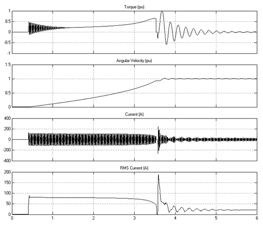 Star-Delta Open Transition Results (70% case)
 Star-Delta Open Transition Results (RMS current, 80% case)
 Star-Delta Open Transition Results (RMS current, 90% case)
From the curves, it is apparent that the motor starting current has been reduced. Reduction of motor starting current is the primary reason for utilising a star-delta starter. Although the starting current has been reduced, the acceleration torque is also reduced, resulting in the motor taking longer to run up to full speed.
The 70% example shows a significant spike at the changeover, resulting in voltage drops which are no better than utilising a direct-on-line starter. Depending on the di/dt and magnitude it can often create worse problems than using simpler direct on starting. This is typical of a badly configured star-delta starter and the reason a closed transition starter is often preferred.
Note: looking at the behaviour of acceleration torque and how any connected mechanical load behaves is often the reason for conducting a study. While we will not be doing so in this post, hopefully the reader can see how this could be accomplished.
As a summary, compared to direct-on-line starting, the main electrical parameters are:
| | Direct-On-Line | Star-Delta |
| Time to full speed, s | 2.7 | 3.7 |
| Full load current, A | 21 | 21 |
| Starting current, A | 166 | 81 |
| Starting current, x (times full load) | 7.9 | 3.8 |
Star-Delta Closed Transition
In closed transition starting resistors, are inserted into the negative end windings ensuring the motor is never disconnected from the supply.
Resistor sizing can be difficult and models such as these can help greatly. For this example resistor size based on a 30% voltage drop across the resistor is chosen:
VLN is the line to neutral voltage (2220 V) and Ia the starting current (81 A). Applying the formula, gives a calculated resistance of R = 0.8148 Ω.
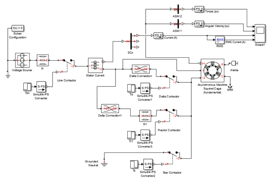 Star-Delta Close Transition Circuit Model
 The star-delta closed transition model is a slight modification to the open transition example, where:
- a delta connected resistor bank (R1) is switched into circuit by Tr1 at the same time as the star contactor is opened (Tr1 = Td)
For brevity, we are only interested in what happens to the current spike in the 70% case.
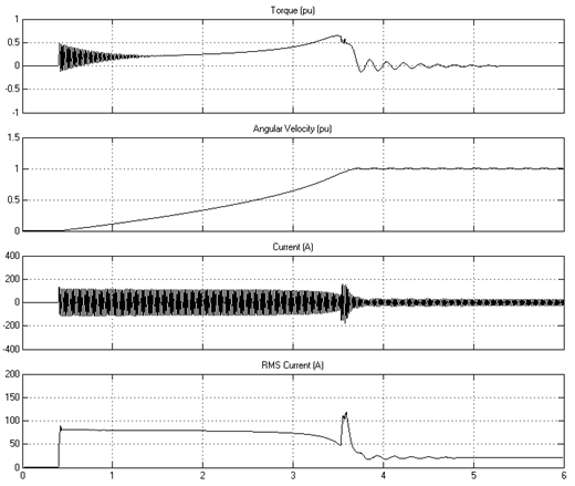 Star-Delta Closed Transition Results (70% case)
As can be seen, the current spike has been significantly reduced, clearly illustrating that even how the effect of resistors improve the characteristics of a badly timed changeover.
Note: The magnitude of starting current is still slightly higher than we would like, but by using the model to adjust the resistor size, it should be possible to reduce this. Optimisation of resistor size (and other components) are benefited by the modelling starting circuits.
Conclusion
As demonstrated, the study of motor starting circuits is not onerous, and yet it provides detailed insight into the functioning of the motor and load while starting and in steady state conditions.
While the example given is simplified, it is just as easy to extend the model to represent real network conditions and/or carry out various 'what-if' scenarios, look at other starting methods or other parameters (for example resistor I2t losses).