Fault Calculation - Per Unit System
| Symbol | | Definition |
![Image(11)_thumb[1] Image(11)_thumb[1]](http://myelectrical.com/Portals/0/SunBlogNuke/2/Windows-Live-Writer/Fault-Calculation---Per-Unit-System_DF80/Image(11)_thumb%5B1%5D_thumb.png) | - | per unit method current base |
![Image(25)_thumb[1] Image(25)_thumb[1]](http://myelectrical.com/Portals/0/SunBlogNuke/2/Windows-Live-Writer/Fault-Calculation---Per-Unit-System_DF80/Image(25)_thumb%5B1%5D_thumb.png) | - | per unit method power base |
![Image(26)_thumb[1] Image(26)_thumb[1]](http://myelectrical.com/Portals/0/SunBlogNuke/2/Windows-Live-Writer/Fault-Calculation---Per-Unit-System_DF80/Image(26)_thumb%5B1%5D_thumb.png) | - | per unit method voltage base |
![Image(17)_thumb[1] Image(17)_thumb[1]](http://myelectrical.com/Portals/0/SunBlogNuke/2/Windows-Live-Writer/Fault-Calculation---Per-Unit-System_DF80/Image(17)_thumb%5B1%5D_thumb.png) | - | per unit method admittance base |
![Image(14)_thumb[1] Image(14)_thumb[1]](http://myelectrical.com/Portals/0/SunBlogNuke/2/Windows-Live-Writer/Fault-Calculation---Per-Unit-System_DF80/Image(14)_thumb%5B1%5D_thumb.png) | - | per unit method impedance base
 - percentage impedance - percentage impedance
 - per unit impedance - per unit impedance
 - actual impedance - actual impedance
 - per unit base impedance - per unit base impedance |
Per unit fault calculations is a method whereby system impedances and quantities are normalised across different voltage levels to a common base. By removing the impact of varying voltages, the necessary calculations are simplified.
To use the per unit method, we normalise all the system impedances (and admittances) within the network under consideration to a common base. These normalised impedances are know as per unit impedances. Any per unit impedance will have the same value on both the primary and secondary of a transformer and is independent of voltage level.
A network of per unit impedances can then be solved using standard network analysis (see the example). From this fault level can be readily determined.
In applying the per unit method, the first step is to select an arbitrary voltage (Vbase) and power (Pbase) base.
Tip: while the base power and voltage be any value, typically it would make sense to select values related to the system under construction (for example 11 kV and 20 MVA may be appropriate for a distribution type system)
Per Unit Method
Having selected a base power and voltage, the base per unit values of impedance, admittance and current can be calculated from:
| Per Unit | Single Phase | Three Phase |
| _thumb_1.png)
| _thumb_1.png)
| _thumb_1.png)
|
| _thumb_1.png)
| _thumb_1.png)
| _thumb_1.png)
|
| _thumb_1.png)
| _thumb_1.png)
| _thumb.png)
|
Dividing a system element by it’s per-unit base value gives the per-unit value of the element, for example

Some times per-unit values are available for a given base kV, but the problem being solved is using a different base. In this instance it is possible to convert the unit:

Fault calculation problems typically deal wit power sources, generators, transformers and system impedances. Per-unit values for these elements can be quickly derived from:
| Element | Per-Unit Value |
| Source impedance |  |
| Generators |  |
| Transformers |  |
| Impedances |  , where V is in kV , where V is in kV |
Example - calculating per unit values
Consider a system of source impedance 4.48 Ω connected to a 20 MVA transformer (11/0.4 kV) at 6% impedance. We want to find the fault level at the transformer secondary.
Selecting Pbase as 20 MVA and Vbase as 11 kV and using the above equations:

and
_thumb_1.png)
_thumb_1.png)
_thumb_1.png)
_thumb_1.png)
the Line-Neutral voltage on the secondary of the transformer is 0.4/√3 = 0.230 kV, giving:
_thumb_1.png)
Three Phase Fault Example

Three Phase Fault Example Per unit analysis can be used to calculate system three phase fault levels and the current distributions. To gain a better understanding, it is worth running through the typical steps required to solve a fault calculation problem.
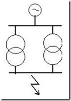
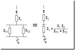
Given the system single line diagram, construct and simplify the per unit impedance diagram.
The fault level at the point under consideration is given by:

Where Zpu, is the total impedance between the source and the fault.

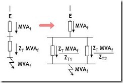
Fault flow through parallel branches is given by the ratio of impedances. As illustrated this can enable fault flows to be found through each branch.

Having calculated the fault flow in each branch, it is then relatively simple to find the current distribution using:

where:

Related Notes