Generator Sizing & Operation Limits
When selecting a generator, there are inherent limits on the active and reactive power which can be delivered. Generators are normally sized for a certain kW at a power factor of 0.8. However, to understand the operation fully, it is necessary to look at the generator reactive power curve.
Generator Operation
 Generator Operation Area
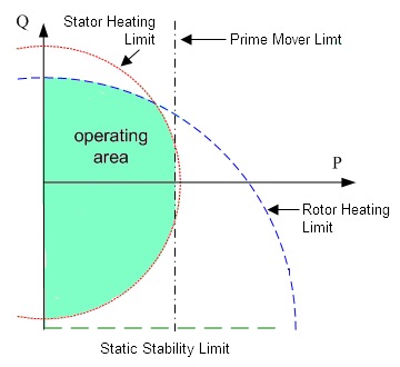
 When selecting a generator, there are inherent limits on the active and reactive power which can be delivered. To illustrate this, the images show typical generator operation limits.
The smaller image depicts active power P, on the x-axis and reactive power Q, on the y-axis. What would be considered the normal stable operating areas for a generator is shown in green. As the generator operating point, measured in terms of active and reactive power , moves out of this region, operation become more unstable.
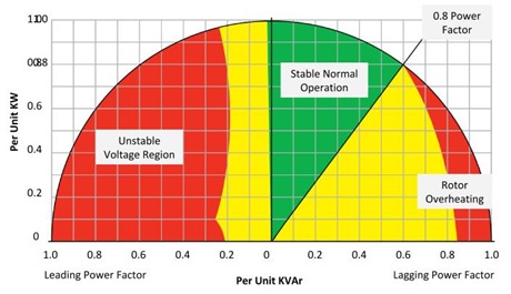
Generators are normally sized for a certain kW at a power factor of 0.8. However, to understand the operation fully, it is necessary to look at the generator reactive power curve. The image below shows similar information as the first image, but with more detail on where various limits apply. Operation within the green area is pretty safe while operation in the red should be avoided. Operation within the yellow is possible, subject to a detailed analysis being carried out..
 Typical generator reactivate power curve
Generator operation for various levels of reactive power, both leading and lagging as shown. It can be seen that a stable operating region lies within a region of lagging power factor from 1 to 0.8. As we move out of this region, we can start experiencing issues. In particular leading power factors can result in unstable operation. Low lagging power factors can result in rotor overheating.
Sizing of Generators
Sizing of generators can be carried out either by hand or using software. For anything but the simplest systems, it is recommended to use manufacturers software so that a generator of adequate size is selected.
While software is often used, a good understanding of the variables which affect the size of a generator, will better ensure that the selected size of appropriate. The key considerations are:
- Loading of the generator - the total connected load has a direct bearing on the ultimate size of any generator. This is probably where most people start in sizing a generator.
- Motor starting - starting of motors results in large current inrush and subsequent generator voltage drops. Any generator needs to be sized such that the level of voltage drop still enables the motor to accelerate the load. There is also short term heating on the generator during this period.
- Power factor - has a direct effect on the operation of the generator as discussed earlier.
- Voltage and frequency - sizing of generators needs to be carried out at the application voltage and frequency.
- Allowable voltage & frequency dips - unlike the grid, generators are not infinite (large) sources. There will be voltage and frequency variations, and the generator needs to be sized to ensure these are below allowable limits.
- Cyclic loading - loads which cycle, place varying demands on a generator. Factoring these into the sizing model will help ensure that generators are not oversized.
- Non-linear loads - non-linear loads (UPS, VFD, etc.) generate high frequency harmonics, which can heat up the generator. In addition, if lightly loaded, these can cause leading power factors.
- Other Considerations - in addition to the above; the type of fuel used, ambient temperature. Load shedding schemes and provision for future growth will all affect the final selected generator size.
In addition to being undersized, it is also possible to oversize generators. At loads below 30%, generators can
During sizing a distinction will also be made between standby and prime generator sets. Standby rated generators are typically based on a limited number of hours operation and have no overload facility. Prime sets and run continuously at the rated load and do have periodic overload capability.
Types of Rating
- Standby - these generators are used for supplying emergency power. They have a limitation on running hours and no overload capability.
- Prime - generators are used to continuously supply permanent power at variable load. Typically they would also have the ability to deliver a 10% overload for one hour.,
- Continuous - similar to prime, continuous generators are used to supply permanent power. These would tend to be used to supply constant (non-varying) loads up to a fixed limit and do not have overload capabilities.