Fault Calculations - Introduction
Fault calculations are one of the most common types of calculation carried out during the design and analysis of electrical systems. These calculations involve determining the current flowing through circuit elements during abnormal conditions – short circuits and earth faults.
Types of Fault
| Symbol | | Definition |
 | - | voltage factor (IEC 60909)
LV, Isc max = 1.1, Isc min = 0.95
MV, LV, Isc max = 1.1, Isc min = 1 |
 | - | steady state fault |
 | - | initial symmetrical fault current
k or k3 - 3-phase fault
k1 - phase to earth (or phase to neutral) fault
k2 – phase to phase fault
k2E or kE2E – phase to phase to earth fault |
 | - | rated current of any motor |
 | - | nominal voltage
 - nominal line to neutral voltage - nominal line to neutral voltage
 - nominal line to line voltage - nominal line to line voltage |
 | - | system voltage |
 | | circuit impedance |
A fault is an abnormal or unintended connection of live elements of a system to each other or to earth. The impedance of such connections are often very low, resulting in large currents flowing. The energy contained in fault currents can quickly heat components, creates excessive forces and can result in devastating explosions of equipment.
Typically we deal with three types of fault:
- Three Phase Faults
- Phase to Phase Faults
- Earth Faults
Typically highest fault current is given by a three phase fault (although there are exceptions).
Standards
IEC 60909 'Short Circuit Currents in Three Phase Systems' describes an internationally accepted method for the calculation of fault currents. IEC 60781 is an adaption of the 60909 standard and applies only to low voltage systems.

IEC 60909 Fault Current In applying these standards, two levels of fault based on voltage factor are typically calculated
- the maximum current which causes the maximum thermal and electromagnetic effects on equipment (used to determine the equipment rating)
- the minimum current (which may be used for the the setting of protective devices)
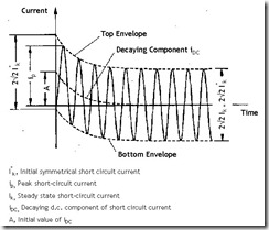
The standards also idealise the fault, enabling each stage to be analysed and understood. The image (click for a larger version), shows this waveform.
Depending on the position within the cycle at which the fault forms, a dc offset will be present, decaying overtime to zero. This creates an initial symmetrical short circuit I''k, which will decay over time to the steady state short circuit Ik.
Three Phase Faults

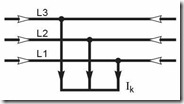
Three Phase Fault In a three phase fault, all three phases (L1, L2 and L3) are shorted together.
To find the fault current at any point in the network, a sum is made of the impedances in the network between the source of supply (including the source impedance) and the point at which the fault is occurs.
To find the fault current Ik, the nominal applied voltage, U0 is divided by the summed impedance Z.

Phase to Phase Faults

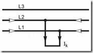
Phase to Phase Fault In a phase to phase fault (L1 to L2 for example), two phases are connected together.
The fault current is again, the nominal applied voltage divided by the summed impedance.
Earth Faults

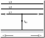
Earth Fault In an earth fault, one phase is directly connected to earth (L1 to earth for example).
To find the value of earth fault current at any point in a network, a sum is made of the earth fault impedances in the network between the source of supply (including source impedance) and the return path impedances.
Use of Tables
Often if it is required to look up a quick ball park figure, it is adequate to use tables. This is particularly the case for low voltage systems. In other cases, actual equipment parameters may not available and it is necessary to resort to typical values. The 'Notes' section of the site contains a selection of tables, which will help in these instances:
Low Voltage Fault Tables
Fault Calculations - Typical Equipment Parameters
Basic Fault Calculations
| Fault Type | Calculation |
| 3-phase fault |  |
| phase-phase fault |  |
| phase-earth fault |  |
One of the simplest ways to look at fault calculations is by the application of Ohm’s law. Knowing the impedance of the fault and the voltage across enables the fault current to be calculated:
Per Unit Fault Calculations
In systems with varying voltage level, per unit calculations enable faults levels to be determined by normalising the system to a common base. This method of calculating fault levels is known as the per unit method or per unit system.
To find out more about this per unit calculations, refer to our note:
Symmetrical Components
For unbalance conditions the calculation of fault currents is more complex. One method of dealing with this is by the use of symmetrical components. In symmetrical components, the unbalance system is broken down in to three separate symmetrical systems, each of which are easily solved.
To find out more about symmetrical components, refer to our note:
IEC 60909 - Short-circuit currents in three-phase a.c. systems
Often when performing short circuit calculations, it is necessary to carry these out against a reference standard. By using a reference standard, calculations are consistent, can be justified and are provided with an audit trail.
IEC 60909 is the international standard for the calculation of short circuit currents. The document specifies a standardised method for the development of short circuit calculations, as well as providing guidance on equipment data.
To find out more about how the standard works, refer to our note:
- Fault Calculation - IEC 60909 - note coming soon
Motor Contributions
During fault conditions motors operate a generators (until the rotation reduces) and will contribution current to the fault. When taking motor contributions into considerations, the IEC 60909 standard gives guidance on how to do this.
To simplify calculations, the contribution of motors to the fault can be disregarded if:

Related Notes