Understanding Circuit Breaker Markings

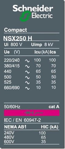
Typical Circuit Breaker Nameplate IEC 60947 is the circuit breaker standard and covers the marking of breakers in detail. Any manufacturer following this standard should comply with the markings.
Name Plate and Breaker Markings
The illustration shows a standard nameplate from a Schneider NSX circuit breaker. Other manufacturers should have similar information on the breaker. The standard requires the following by information to be identified and marked on the circuit breaker.
Visible and legible when breaker installed:
- rated current (In)
- suitability for isolation, if applicable
- indication of the open and closed positions
Marked, but need not be visible when installed:
- manufacturer's name or trade mark and circuit breaker type designation or serial number
- manufacturing standards the breaker complies with
- utilization category
- rated operational voltage (Ue)
- rated impulse withstand voltage (Uimp)
- rated frequency and/or the indication d.c.
- rated service short-circuit breaking capacity (Ics) at corresponding rated voltage (Ue)
- rated ultimate short-circuit breaking capacity (Icu) at corresponding rated voltage (Ue)
- rated short-time withstand current (Icw), and associated short-time delay (for utilization category B)
- line and load terminals (unless their connection is immaterial)
- neutral pole terminal, if applicable ( by the letter N)
- protective earth terminal, where applicable, by symbol
- reference temperature for non-compensated thermal releases, if different from 30 °C
Additional Circuit Breaker Information
In addition to the above the following should be either marked on the circuit breaker or made available in technical documentation:
- rated short-circuit making capacity (Icm)
- rated insulation voltage (Ui),
- pollution degree if other than 3
- conventional enclosed thermal current (Ithe) if different from the rated current
- IP Code, where applicable
- minimum enclosure size and ventilation data (if any) to which marked ratings apply
- details of minimum distance between circuit-breaker and earthed metal parts for circuit breakers intended for use without enclosures
- suitability for environment A or environment B, as applicable
- r.m.s. sensing, if applicable
Auxiliary Devices
Any auxiliary devices should be marked or technical information provided with the following:
- rated control circuit voltage and frequency of any closing
- rated control circuit voltage and frequency of any shunt release and/or under-voltage release
- rated current of indirect over-current releases
- number and type of auxiliary contacts and rated frequency
- rated voltages of auxiliary switches (if different from those of the main circuit)
Symbols
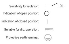
The standard identifies the following symbols in connection with circuit breaker markings:

Hopefully now, the next time we look at a break it should all make sense.