Alternating Current Circuits
Alternating current (a.c.) is the backbone of modern electrical power distribution. In this article I’ll be pulling some of the more important concepts together. It is a work in progress and I’ll be adding to it bit by bit as I start closing pages down in the Wiki. Hopefully by the time the Wiki is fully depreciated, we should have a reasonable article here.
Alternating Current Theory

Sine wave Alternating voltage or current is in the form of a sine wave and is given by:
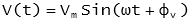
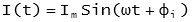
and
Where:
V(t) - is the instantaneous voltage at time, t
I(t) - is the instantaneous voltage at time, t
Vm - is the maximum value of instantaneous voltage
Im - is the maximum value of instantaneous current
ω - is the angular frequency in radians
 - is the phase angle of the voltage
 - is the phase angle of the current
The number of full cycles per second is the frequency (f) and is measured in Hertz (Hz). The period (T) of a sine wave is the time to complete on cycle in seconds and is related to the frequency by:
 |
Note: In the Europe, the frequency is 50 Hz (period to 20 mS), while in the US it is 60 Hz (period 16.67 mS). |
The angular frequency ω, is given by:

RMS and Average Values
The average voltage or current of a pure sine wave is zero.
Even though the average is zero the power delivered by an AC source is not zero.
The root-mean-square (rms) values of current voltage and current equate the power delivered by the AC circuit.

The average value of a sine wave is 0.637 of the maximum. | RMS Theory The RMS value of a function is the root of the mean of the square of the function. This is expressed mathematically as: In electrical engineering this is important as it relates to a value of voltage (V) or current (I), which when multiplied together gives power: 
The RMS value can be worked out for any periodic function. For common electrical waveforms this gives: | | | RMS Value | | Sine Wave |  |  | | Square Wave |  |  | | Saw-tooth Wave |  |  | |
Complex Power
Real, reactive power and power factor can be explained using different concepts. Sometimes it is convenient to use the concept of complex power. In an electrical system, if the voltage and current are treated as vectors, these can be expressed in complex numbers. The complex power S, of the system is then given by:
where:
P is the complex power in VA
V is the voltage in complex form in V
I* is the conjugate of the current in complex form (the imaginary part is multiplied by -1) in A

Complex Power Complex power S, is a vector and is commonly represented as:
where:
S is the complex power in VA
P is the real power transmitted in W
Q is the reactive power transmitted in VAr
j is the complex operator √-1
The quantity P, represents the real power transmitted in the system. This is the power that actually does work (i.e. rotating motors, heating homes, etc.). The reactive power Q, does not do actual real work, but is responsible for maintaining the magnetic and electric fields of the electrical system. These fields provided the energy storage mechanisms necessary for the distribution system to work. The magnitude of the complex power S, is often referred to as apparent power.
The ratio between the real and apparent power is the power factor of a system:
If the current is lagging the voltage in phase (for example in an inductive circuit) the power factor is said to be lagging. Conversely if the current leads the voltage the power factor is said to be leading. For a power factor of 1, the real and apparent power will be the same, with the reactive power being equal to zero. As the power factor is reduce, more reactive power in the system is required. Generation of reactive power required additional equipment, increasing transmission system costs and operating energy loss. By ensuring high power factors these costs and loses are reduced.
AC System Components
The three main components to an alternating current (ac) system are resistance, inductance and capacitance.
Resistance
The resistance of an alternating current circuit is denoted by the symbol R.
Inductance
The impedance of a inductor XL is given by:

where:
 - is the angular frequency
f - is the frequency
L - is the inductance in henry, H
j - is the imaginary unit
Q-factor of an Inductor
While in an ideal inductor the resistance is zero, in practice there is always some resistance. Loss in the resistance makes the inductor inefficient. The ratio of inductive reactance to resistance is the Q-factor; the higher the value the closer to an ideal conductor:
For more on inductance, see the Notes Post on Inductance
Capacitance
The impedance of a capacitor Xc is given by:

where:
C - is the capacitance in Farad
See also: Capacitor Theory
Impedance of a Circuit
Impedance (Z) is the resistance in ohms (Ω) to the flow of electric current in a circuit:

where:
R - is the resistance of the circuit, Ω
X - is the reactance of the circuit, Ω
Note: Admittance (Y) is the inverse of impedance (i.e. Y=1/Z). The unit of admittance is the siemens (S)
References
- [1] William D.Stevenson, "Elements of Power System Analysis", McGraw-Hill, 1982
- [2] The IDC Engineers Pocket Guide, First Edition, Volume 5