Laplace Transform 

By on

Laplace transforms and their inverse are a mathematical technique which allows us to solve differential equations, by primarily using algebraic methods. This simplification in the solving of equations, coupled with the ability to directly implement electrical components in their transformed form, makes the use of Laplace transforms widespread in both electrical engineering and control systems engineering.

This note is a recap/review of Laplace theory and reference which can be used while carrying out day to day work.  It is not an introduction or tutorial and does assume some prior knowledge of the subject.

Theory

The Laplace transform, named after Pierre-Simon Laplace who introduced the idea is defined as:

  F(s)=L{ f(t) }= 0 e st f(t)dt

where: S = σ + iω,  (σ and ω as real numbers)

the result is a function of s, and the transform can be written as:

  F(s)=L{ f(t) }

Give the transform, the inverse can be found from:

  f(t)= L 1 { F(s) }= 1 2πi lim T0 γiT γ+iT e st F(s) ds

While we can use the above equations to find the Laplace transform (or it's inverse) for a given function, in practice the use of table is more common.  The following table lists the more common transforms and their inverse:

Time Function
f(t)
Laplace Transform
F(s)
 24f8e9f56fc5bcb3a2ad3c79ba3a2c7b, unit impulse 1
 b91f4842173563a0ac7a44d398c6e1e1, unit step  78a2bb03e604d1bdf9c505849c2ae6de
21e0db562c07c8e246d62c28a07d063b  f576f493f417d1092129223e114a8c22
 aa0c14b75d13ad40e5e2a7d2d627890a 33a7445026b76fbb16207a3f77582a87
 089349ec19fad35222e8a1218de1933d  e3828a2f8700399051c4d5d8664bc3e8
 51a60244b573f30d269613c82f34f9bf  a341b85df1e9f59d93431ad944646b08
05f57ce3016333e9151d8c438f48148d  03f27ed4bac3cc00c62ec23d4aafdddf
605a02692c1fd6352c81824cfc97dbc2 f584ebe7fd97cd9ab28447e7eb7746ea
 93e756668096c0782590fa2eba7ea57d  6c0345e0a8343cfd5e5bc95bfdb2e03e
 9f34f62bd309234b2b3f4940ee636a93 0ccc3e4e546d9c5477ccce0f559eb4ce

43ef95a5520a48878531b1734c482388

ab58c94ae4103af54499df9a2833a682
64d9325b542e87b876b021214050ad41 b33b09e660a44acc6830c7ab792c28bc
bf3ed07ae2e94b31653d5e1f3268774d 64360a06e8fe2c32ce4e0c8694a0ac6b
0ae598d99559be0ac138add67d504f9d  7acae834dc327fea2979ad06e512d5d8
ec56a04d2acbe81be489ddb25c14b49b d9eb6678fc7327d0117b9a76a499a2e4
       

ef96c80a1e971431c1a5277a1b6a4e7c  

where0e380d4a2ed6c0d701338f24b2f6743a

    3f7b2b01839de3266a91d24d23cfe02e  

Useful Operations

     
Linearity    f826856a62de1b0d6d8d5b100a07fdc3
Multiplication (by constant)  7da89b783d11bd54aeb5c074392b0e1e
Real Shift Theorem  e0f537e413836524d5b02939b92a8f59
Complex Shift Theorem  85d3dffb7c281d3a8546006235c1c174
Scaling  75d7e22ec3ba78c04b4803e2f09f72ad
Derivative (1st)    3cff21371695158da24a4d99fa79342b
Derivative (nth)    dcc2512546394287d95ec5aab9601bd7
Integral    4f8dbbf016f40cf9ec89a3331c949a17
Convolution    convolution
   Heaviside (step) Function

 heavisideDelayed

heaviside

Partial Fractions

In finding the inverse transforms, it is helpful if the equation to be solved is expressed as a sum of fractions.  Partial fractions are a way to achieve this and the process is called resolving partial fractions. 

To be able resolve partial fractions, the numerator needs to be of lesser degree than the denominator and depending on the type of partial fraction:

Linear factors in the denominator:

qf1


Repeated linear factors in the denominator:

qf2


Quadratic factors in the denominator:

qf3

Example: the following example illustrates how to use the method of partial fractions to resolve a simple equation using linear factors. Ffind the partial fractions of:

qfEx1 

which can be resolved into

qfEx2

From the above, it can be seen that: 

qfEx3

By choosing values of s to make A or B equal to zero (s = -2, s = –1), the above can be solved to give A (=4) and B (=-3), giving us the final solution:

qfEx4

Application

One of the great things about Laplace Transforms is that the core electrical quantities (resistance, inductance and capacitance) can be easily represented in their Laplace form; simplifying the solving of circuits.  The table below summaries the time and Laplace representation of each quantity:
 
Time domain Laplace domain
v(t) i(t) F(s) V(S) I(S)

Resistor
 
04-01-01 Resistor

   R   
56990129714dfb195b69dfad602511ea f1ccdc5f158f21bc3347c73a9b065de8 b46abc75621b291c72850ffb405d9099 b4e6f42138630ccb57d38da25c54c8ff e0fb899bf1623d271e7cbb03d2e67485

Inductor 

04-03-01 Inductor
 
L
  L= di(t) dt 91a93a21c5f73448168e39569b6b4cb5 ecb05569472289eea4bfffeea7e26e85  c5c2887af36ca17002855c1aacbde9a5 6a4bca16e957854b91d846e1b706f762

Capacitor

04-02-01 Capacitor
 
C
479ddeb4a8e95c242f6668fa47455fb4 1852c442503120433a2c1e1e20c589f4

 086863e1420d00f497810ed31752be9e

79686871d2a440fc8b2948925ba159b4 5323d1fd4831fe18a61ea97e53f4bd4d


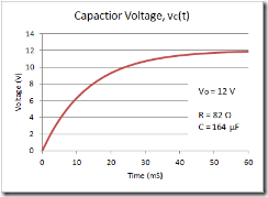
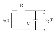
laplaceRC_cctExample:  consider a series circuit consisting of a resistor and capacitor as shown. A step voltage v(t) equal to V0 is applied at time zero.  What is the form of the voltage across the capacitor, vc(t).

To represent the input voltage, we can use the Heaviside (step):

v_t

v_t_chartFrom the above table, the Laplace transform of the current, i through the circuit can be written directly as:

I_s

and the Laplace voltage across capacitor as:

vc_s

Rearranging the equation and taking the inverse Laplace transforms, gives:

vc_t


Steven McFadyen's avatar Steven McFadyen

Steven has over twenty five years experience working on some of the largest construction projects. He has a deep technical understanding of electrical engineering and is keen to share this knowledge. About the author

myElectrical Engineering

comments powered by Disqus


Hazardous Areas – IEC and NEC/CEC Comparison

Depending where in the world you work, you are likely following one of two standards International Electrotechnical Commission (IEC) National...

Voltage Levels – Confused?

I was having a conversation the other day about voltage levels.  While everyone was in agreement that low voltage was 1000 V and less, there was more confusion...

Introduction to Traction Substations

Following on from my post on railway electrification voltages, I thought an introduction to traction substations would be a good idea. Traction substations...

The ac resistance of conductors

In a previous article I looked at the dc resistance of conductors and in this article we turn our attention to ac resistance. If you have not read the...

Cable Sizing Software

When sizing cables nearly, everyone uses some form of software. This ranges from homespun spreadsheets to complex network analyses software. Each has its...

Contribute to myElectrcial

Have an opinion or something to say, want to ask or answer questions, share your knowledge then use our site to do it . As a community of people interested...

Surface Treatment – Ladders, Trays and Baskets

Steel ladders, trays and baskets form the backbone of cable containment systems. Often these items need some form of surface treatment to prevent corrosion...

Generator Sizing & Operation Limits

When selecting a generator, there are inherent limits on the active and reactive power which can be delivered. Generators are normally sized for a certain...

Introduction to Current Transformers

Current transformers (CTs) are used to convert high level currents to a smaller more reasonable level for use as inputs to protection relays and metering...

Always Use PPE

A lot of our members work in countries where PPE (personal protective equipment) is regulated or they work for companies/organizations which take employee...

Have some knowledge to share

If you have some expert knowledge or experience, why not consider sharing this with our community.  

By writing an electrical note, you will be educating our users and at the same time promoting your expertise within the engineering community.

To get started and understand our policy, you can read our How to Write an Electrical Note