Fault Calculations - Typical Equipment Parameters
A frequent problem in fault calculations is the obtaining of equipment parameters. While it is always preferable to use the actual parameters of the equipment, sometimes these are not available. In this instance it is necessary to resort to the use of typical parameters.
This note is intended to become a collection of typical parameters. If there is something missing or needs adding, please leave a comment in the discussion.
HV Network Impedance
Impedance of HV network referred to LV side of transformer
| Psc |
Uo (V) |
Ra (mΩ) |
Xa (mΩ) |
| 250 MVA |
420 |
0.106 |
0.71 |
| 500 MVA |
420 |
0.053 |
0.353 |
Low Voltage Power Transformers
Transformer Short Circuit Impedance
Typical values short circuit impedance, USC for different kVA ratings (HV winding < 20 kV)
| |
Type of Transformer |
| transformer rating |
oil-immersed |
cast-resin |
| 50 to 630 |
4% |
6% |
| 800 to 2500 |
6% |
6% |
Transformer Impedance (400 V)
Resistance, reactance and impedance for typical transformers (HV winding <20 kV)
| transformer rated power (kVA) |
50 |
100 |
160 |
250 |
315 |
400 |
500 |
630 |
800 |
1000 |
1250 |
1600 |
2000 |
2500 |
| oil-immersed |
Usc % |
4 |
4 |
4 |
4 |
4 |
4 |
4 |
4 |
6 |
6 |
6 |
6 |
6 |
6 |
| |
Rtr mΩ |
95.3 |
37.9 |
16.2 |
9.2 |
6.9 |
5.1 |
3.9 |
2.9 |
2.9 |
2.3 |
1.8 |
1.4 |
1.1 |
0.9 |
| |
Xtr mΩ |
104.1 |
59.5 |
41.0 |
26.7 |
21.3 |
16.9 |
13.6 |
10.8 |
12.9 |
10.3 |
8.3 |
6.5 |
5.2 |
4.1 |
| |
Ztr mΩ |
141.1 |
70.5 |
44.1 |
28.2 |
22.4 |
17.7 |
14.1 |
11.2 |
13.2 |
10.6 |
8.5 |
6.6 |
5.3 |
4.2 |
| cast-resin |
Usc % |
6 |
6 |
6 |
6 |
6 |
6 |
6 |
6 |
6 |
6 |
6 |
6 |
6 |
6 |
| |
Rtr mΩ |
|
33.5 |
18.6 |
10.7 |
8.2 |
6.1 |
4.6 |
3.5 |
2.6 |
1.9 |
1.5 |
1.1 |
0.8 |
0.6 |
| |
Xtr mΩ |
|
100.4 |
63.5 |
41.0 |
32.6 |
25.8 |
20.7 |
16.4 |
13.0 |
10.4 |
8.3 |
6.5 |
5.2 |
4.2 |
| |
Ztr mΩ |
|
105.8 |
66.2 |
42.4 |
33.6 |
26.5 |
21.2 |
16.8 |
13.3 |
10.6 |
8.4 |
6.6 |
5.3 |
4.2 |
Synchronous Machines
Performance Under Fault Conditions
Sub-transient emf: 
Transient emf: 
S
ynchronous emf: 
Fault current:

Typical Machine Reactances
Typical Machine Reactances (& Time Constants
| |
Cylindrical Rotor
Turbine Generators |
Salient Pole Generators |
| |
Salient Pole
Synchronous
Condensers |
Conventional |
Direct
Cooled |
4 Pole |
Multi-Pole |
| Synchronous |
| Direct axis |
Xd |
pu |
1.6-2.0 |
0.8-1.0 |
2.0-2.3 |
2.1-2.4 |
1.3-2.1 |
1.3-1.5 |
| Quadrature axis |
Xq |
pu |
1.0-1.25 |
0.5-0.65 |
1.95-2.1 |
1.95-2.25 |
0.6-1.2 |
0.8-1.0 |
| Transient |
| Reactance |
Xd' |
pu |
0.3-0.5 |
0.2-0.35 |
0.18-0.25 |
0.27-0.30 |
0.15-0.35 |
0.4-0.5 |
| Short circuit |
τd' |
s |
1.5-2.5 |
1.0-2.0 |
0.75-1.0 |
0.75-1.0 |
0.8-1.2 |
0.8-1.2 |
| Open circuit |
τdo' |
s |
5-10 |
3-7 |
4-8 |
6-9.5 |
4-8 |
3-7 |
| Sub-transient |
| Direct axis |
Xd'' |
pu |
0.2-0.4 |
0.12-0.25 |
0.11-0.13 |
0.19-0.23 |
0.1-0.25 |
0.2-0.35 |
| Quadrature axis |
Xq'' |
pu |
0.25-0.6 |
0.15-0.45 |
0.11-0.13 |
0.19-0.23 |
0.14-0.35 |
0.2-0.35 |
| Short circuit - direct axis |
τd' |
s |
0.04-0.09 |
0.05-0.10 |
0.015-0.025 |
0.02-0.03 |
0.02-0.04 |
0.02-0.07 |
| Open circuit - direct axis |
τd'' |
s |
0.07-0.11 |
0.08-0.25 |
0.015-0.025 |
0.02-0.03 |
0.04-0.07 |
0.02-0.07 |
| Short circuit - quadrature axis |
τq'' |
s |
0.04-0.6 |
0.05-0.6 |
0.015-0.025 |
0.02-0.03 |
0.10-0.15 |
0.02-0.07 |
| Open circuit - quadrature axis |
τq0'' |
s |
0.1-1.2 |
0.2-0.9 |
0.015-0.025 |
0.02-0.03 |
0.3-0.7 |
0.1-0.2 |
| Other Reactances |
| Negative sequence |
X-ve |
pu |
0.25-0.5 |
0.14-0.35 |
0.11-0.13 |
0.19-0.23 |
0.12-0.3 |
0.2-0.35 |
| Zero sequence |
Xo |
pu |
0.12-0.16 |
0.06-0.10 |
0.05-0.075 |
0.11-0.16 |
0.03-0.10 |
0.1-0.2 |
Cables
where:
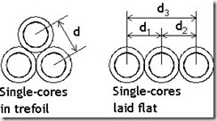
d = distance between centre
r = geometric mean radius
a = cross sectional area (mm)
