Power Factor

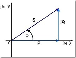
Power Factor Power factor is the ratio between the real power (P in kW) and apparent power (S in kVA) drawn by an electrical load.
The reactive power (Q in kVAr) causes the real and apparent power to be displaced from each other. Reactive power provides the necessity for electric and magnetic fields to enable the power system to work.
In addition to being the ratio of real power to apparent power, the power factor can also be express as the cosine of the angle between the two.

If the reactive power of the load is inductive, the real power will lag the apparent power and the power factor will be lagging. If the reactive power is capacitive the power factor will be leading.
In it's simplest form power factor, can also be considered a measure of the useful work obtained from a power system
Three phase power factor and single phase power factor follow the same concepts
For a theoretical discussion of power factor, see the section on Complex Power on the Alternating Current Circuits note.
Typical Power Factors
Average Power Factor values for the most commonly used plant, equipment and appearances:
| plant and appliances | cos φ | tan φ |
| induction motor - loaded at 0% | 0.17 | 2.80 |
| induction motor - loaded at 25% | 0.55 | 1.52 |
| induction motor - loaded at 50% | 0.73 | 0.94 |
| induction motor - loaded at 75% | 0.80 | 0.75 |
| induction motor - loaded at 100% | 0.85 | 0.62 |
| lamps incandescent | 1.0 | 0 |
| lamps fluorescent (uncompensated) | 0.5 | 1.73 |
| lamps fluorescent (compensated) | 0.93 | 0.39 |
| lamps discharge | 0.4 to 0.6 | 2.29 to 1.33 |
| oven resistance elements | 1.0 | 0 |
| oven induction heating (compensated) | 0.85 | 0.62 |
| oven dielectric heating | 0.85 | 0.62 |
| resistance type soldering machines | 0.8 to 0.9 | 0.75 to 0.48 |
| arc-welding fixed 1-phase | 0.5 | 1.73 |
| arc-welding motor-generator set | 0.7 to 0.9 | 1.02 to 0.48 |
| arc-welding transformer-rectifier set | 0.7 to 0.8 | 1.02 to 0.75 |
| arc furnace | 0.8 | 0.75 |
Source: Groupe Schneider - Electrical installation guide
(According to IEC International Standards), 1996
Harmonic Distorted Waveforms
Example - true power factor
A load is operating with a displacement power factor of 0.875 and THD of 13.4%. What is the true power factor?
The distortion power factor is given by:
_thumb.png)
Resulting in a true power factor of:
_thumb.png)
Power factor as set up above assumes a sinusoidal wave form. In a modern power system with the growth of power electronic devices, the waveform is generally not sinusoidal. In this instance the definition of power factor becomes a little more complicated.
- displacement power factor - is the power factor of the 50 Hz fundamental for a harmonic distorted waveform
- distortion power factor - is the amount the displacement power is reduced due to harmonic content
- true power factor - is the actual power factor, taking into account the harmonic distortion
In a non-sinusoidal waveform the harmonic content reduces the power delivered to the load. True power factor will always be less than the displacement power factor. The ratio of the true power factor to the displacement power factor is the distortion power factor. For purely sinusoidal waveforms the distortion power factor is always 1.
If the total harmonic distortion is know, then the distortion power factor can be found from:
_thumb.png)
_thumb.png)
Power Factor Correction
Calculation of Required kVAr
Existing Situation is defined as load P in kW with power factor pf1 (assume lagging)
Leading to, complex power S1 in kVA

Current Phase angle φ1 is given by:

The desired situation is defined as new power factor pf2
New Phase angle φ2 is give by:

Required compensation Q2 in kVAr:
 and
and 
Numerical Example
Existing Situation: P = 450 kW pf1 = 0.83
S1 = 450/0.83 = 542 kVA
φ1 = cos-1(0.83) = 33.9 degrees
Desired Situation: pf2 = 0.95
φ2 = cos-1(0.95) = 18.2 degrees
Calculation Results:
Q2 = 450 * (tan(33.9)-tan(18.2)) = 154 kVAr
S2 = 450/0.95 = 473 kVA (12.7% reduction)
By improving the power factor, power supply authorities need to generate less reactive power and power distribution systems become more efficient. Power supply authorities often charge a penalty for power factor and it can be financially beneficial for the owner of equipment to provide systems to improve their power factor.
Power factor correction is typically carried out by the addition of capacitors – creating reactive power 180o out of phase with that created by the loads (typically inductive).
Power factor correction may be applied as bulk correction at the main plant switchboard or installed locally at each load.


If the kW is to remain constant then:

and

giving:


Power Factor Correction Tool

Power Factor
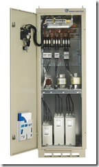
Correction Unit The calculation of the amount of reactive power required to achieve a given improvement is relatively easy to calculate.
To assist in the calculation of required power factor compensation we have added a power factor correction calculation tool to our site. See the links below for details.