Electromechanical Relays
Electromechanical relays have been the traditional backbone of electrical protection systems. While over recent years these have been replaced by microprocessor based numerical devices, there are still many older electromechanical relays in service.
Evolution
Mechanical relays developed in the 1800s were the first form of electrical protection. While still being reliable and widely used these were superseded by static relays in the early 1980s. Static relays have no moving parts (hence the name) and operated on the basis of analogue circuitry. More recently static relays have been superseded by first digital relays and now numerical microprocessor based devices.
Tripping Curves
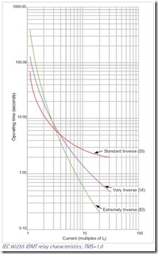
IEC 60255 Characteristics
 The IEC 60255 standard defines four standard current time characteristics – standard inverse (SI), very inverse (VI), extremely inverse (EI) and long-time inverse. Each characteristic can be calculated from:

where:
t = tripping time in (S)
I = fault (actual) secondary CT current (A)
Is = relay pick-up current setting)
TMS = time multiplier setting
| Characteristic |
α |
K |
| Standard Inverse |
0.02 |
0.14 |
| Very Inverse |
1.0 |
13.5 |
| Extremely Inverse |
2.0 |
80 |
| Long-time Inverse |
1.0 |
120 |
Relay characteristics are sometimes classified according to the tripping time at 10 times the setting current (i.e. [3s/10] - a standard inverse curve which will trip in 3 seconds at 10 times the current setting). Tripping times for the various relays are:
| Standard Inverse (SI) |
[3s/10] or [1.3s/10] |
| Very Inverse (VI) |
[1.5s/10] |
| Extremely Inverse (EI) |
[0.8s/10] |
| Long Time Standard Earth Fault |
[13.3s/10] |
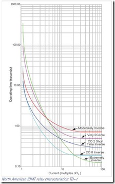
North American Characteristics
 Current time characteristics in North America as classified as IEEE Moderately Inverse, IEEE Very Inverse, IEEE Extremely Inverse, US C08 Inverse and US CO2 Short Time Inverse. These are given by:

where:
t = tripping time in (S)
I = fault (actual) secondary CT current (A)
Is = relay pick-up current setting
TD = time dial setting (multiplier)
| Characteristic |
α |
β |
K |
| IEEE Moderately Inverse |
0.02 |
0.114 |
0.0515 |
| IEEE Very Inverse |
2.0 |
0.491 |
19.61 |
| IEEE Extremely Inverse |
2.0 |
0.1217 |
28.2 |
| US CO8 Inverse |
2.0 |
0.18 |
5.95 |
| US CO2 Short Time Inverse |
0.02 |
0.01694 |
0.02394 |
Setting Example (IEC 60255)
An 1000 Amp breaker protected by relay with Standard Inverse characteristic. The relay pick-up current value is set at 0.8, time multiplier setting is 7 and the fault current is 8000 A. What will be the tripping time?
- - from the table α = 0.02, K = 0.14
- - pick-up current setting = 1000 A x 0.8 = 800 A
- - using the IEC 60255 equations, the tripping time is:

We also have an online IDMT Tripping Time calculator.
CDG11/16 Curves
If you have the 3sec relay's trip curve, you can just multiply the time with 1.3 and divide the answer with 3. That is the time for the 1.3sec relay.
GEC / English Electric / Alstom /Areva
Labelling the model from left to right, using number CDG31 etc. 1=C, 2=D c=G etc.:
- operating quantity (C - current, D - differential, V- voltage)
- basic movement (D - induction disc, M - balanced armature, T - static)
- Application (G- general or generator, E - earth, U - definite time, F - flag, M - motor, D - directional)
- number of units (ie CDG3x is a 3 element / unit CDG relay)
- characteristic (for CDG, 1= std inverse (3s), 2= long time delay, 3=very inverse (1.55s), 4=extremely inverse (0.6s), 6=Long Time Standard Earth Fault)
- case size (15 different cases, A=size 1 draw out, 10 terminal etc.)
- case mounting (F=flush etc.)
- identification (identifies rating, contact arrangement etc. 2= 'metricated')
- suffix ('5' is for 50Hz only relays, '6' for 60Hz)
For a full list refer to publication MS/5100/2 from English Electric
The company history has changed over the last few years. English Electric became GEC and subsequently GEC-Alstom. Recently the company has now been acquired by Areva.
example - CDG 34EG0022A5 is a current operated, induction disc general relay, with three extremely inverse elements and is a 50 Hz unit.
Stabilising Resistors
If current transformers are connected in a residual circuit, saturation of one or more of the transformers during transient events may result in large spill currents. Particularly with high impedance relays, this may cause the the relay to falsely operate. To achieve stability under these conditions, stabilising resistor|resistors are added to increase the minimum relay operating voltage.
Rule of thumb for sizing of resistor:
try to drop:  at
at  ,
,
that is:

Where:
R = stabilising resistor value
Vk = knee voltage of CT
Ipk = relay pickup current
Alternatively the stabilising resistor can be calculated by using:

where:
VA = relay burden
Ir = relay setting current
Note: The power rating of the stabilising resistor should be chosen taking into consideration the expected magnitude and duration of the current through the resistor.