Introduction to Cathodic Protection

Sacrificial aluminium anodes on a ship
Image Source: Cathodic Marine Engineering If two dissimilar metals are touching and an external conducting path exists, corrosion of one the metals can take place. Moisture or other materials acting as an electrolyte between the metals create an electrochemical cells (similar to that of a battery). Depending on the metals, one will act as a cathode and one as an anode of the cell.
Under this arrangement, stray d.c. currents will flow. In the same was a a normal cell, an electrochemical reaction takes place and there is a resulting corrosion of the anode.
In practice, while it could be two dissimilar metals (steel aluminium for example), corrosion could also be a result of microscopic differences in composition of the surface of a single metal.
Cathodic protection works be converting all anodes which are likely to corrode the cathodes. There are two principle methods of doing this:
- attaching a more active metal to form a new anode (making the existing anode the cathode) - resulting in the new material (sacrificial anode) being corroded rather than the protected material
- injection of a a d.c. current (impressed current) uses an anode connected to an external d.c. source to provide the protection
History: it was the English Chemist, Sir Humphrey Davis (1778-1829), who first proposed the concepts of cathodic protection. The first application was to protect the copper plating of British naval ships in 1824[1].
Sacrificial Anode
This is the practice of using a more active metal (sacrificial anode) connected to a structure to be protected, knowing that this metal will be corroded. One example of this would be the use of aluminium sacrificial anodes to protect steel structures in seawater.
Sacrificial anodes need to be electrically connected to the structure being protected.
Note: galvanised steel cable trays and trunking are commonly used. Here a sacrificial coating of zinc is applied which acts acts the anode, preventing corrosion.
Impressed DC Current

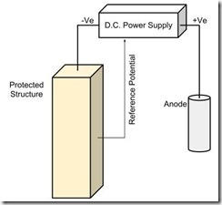
Principle of ICCP Impressed current cathodic protection (ICCP) forces the structure to be protected to become the cathode by connection to an anode and injection of a direct current. The d.c. power supplies typically vary the current to achieve a required protection potential.
In ICCP systems, anodes can range from low end consumable metals to more exotic materials which will exhibit little or no corrosion.
Cathode and Anodes
When two metals are connected, determination of which will be the cathode and anode is made by looking at the relative galvanic potentials of each material. Of the two materials, the metal with the lowest potential will be the anode.
When measuring metals to find their galvanic potential each needs to be measured against a common common cathode (hence the term "Anodic Index" is often used). The following table shows typical galvanic potential of several metals as measured using a gold anode.
If measured against a different cathode, while the values of the galvanic potentials would be different, it is the relative difference in potential between the two metals under consideration in any situation which is important.
| Metal | Potential |
| Gold | 0.00 (most cathodic) |
| Rhodium | -0.05 |
| Silver | -0.15 |
| Nickel | -0.30 |
| Copper | -0.35 |
| Brass & bronzes | -0.40 to -0.45 |
| Stainless Steels | -0.50 |
| Chromium Plated | -0.60 |
| Tin | -0.65 |
| Lead | -0.70 |
| Aluminium (wrought) | -0.75 to -0.90 |
| Iron, wrought | -0.85 |
| Aluminium (cast) | -0.95 |
| Zinc | -1.20 to -1.25 |
| Magnesium | -1.75 |
| Beryllium | -1.85 (most anodic) |
The amount of potential difference required between metals for corrosion to occur varies and is defendant on the environment. As a rule of thumb, many people take an 0.25 V difference of normal environments, 0.5 V where the humidity (and temperature) are controlled and 0.15 V for more harsh industrial environments[1].
As an example of using the table, we can see the potential difference between copper and aluminium is of the order 0.6 V, giving a combination which is to be particularly avoided. In practice special bi-metalic connections need to be employed whenever aluminium conductors are to be connected to copper conductors.
References: