Lightning Protection and Earth Electrode Resistance
 Most installations involve some form of lightning protection system which is connected to an earth electrode. The function of the earth electrode is to dissipate the lightning strike safely in to the ground. Often the performance of the earth electrode is specified and verified by stating a maximum resistance and ensuring that the installed system meets this. Resistance is easily understood and an easy property to measure. However, it is only indicative of the performance of the earth electrode under lightning conditions. Other parameters have a more signification effect.
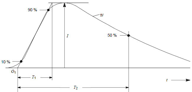
The detailed analysis of a system is relatively complicated. However, it is fairly easy to examine some of the concepts and see how resistance fits into the overall picture. The attached image shows a standard short stroke (duration less than 2 ms) as defined by IEC 62305 [1]. Although lightning strokes will be different, the important thing is the fast di/dt on the rise. Actual parameters vary stroke by stroke, but for a typical first stroke the mean peak current I is 33.3 kA with a dt/dt30/90% of 24.3 kA/μs [2][3].
We can use a a typical earth electrode specification of maximum resistance 10 Ω, achieved by using an earth rod to illustrate some concepts. Typically an earth rod will have an inductance of 5x10⁻⁶ H/m [4]. If we assume the rod is 5 m long then the induced voltages due to resistance Vr and inductance Vl during the initial rise are:
and
As can be seen the voltage due to the inductance is twice that due to the resistance. A lightning peak of 65 kA or earth rod of 10 m the difference in voltage drops would be further exaggerated. This clearly illustrates the importance of inductance in the design of any lighting protection earth electrode. The use of resistance itself is not an accurate measure of performance.
This is further complicated by soil ionizations. Due to the nature of lightning surges, soil ionization is likely to take place, reducing the apparent resistance [5]. The effect of this is to reduce resistive voltage drop and further increase the importance of the inductance of the system.
The lighting stroke can also be looked at as a traveling wave. In this instance the current will have to contend with the surge impedance  . In this analysis the resistance has no effect and it can be noted that the most efficient earth electrode system is one with a low inductance and high capacitance. An earth rod performs poorly in this regard and a better earth electrode system is a mesh type arrangement.
While the above examples are conceptual, they do illustrate the influence of inductance, capacitance are important on the performance of a lighting protection system and that of resistance is less so. Good lightning earth electrode design should go beyond merely specifying a performance parameter based on resistance.
References
- [1] - IEC 62305 'Protection against lightning - Part 1 General Principals', Annex A, 2006
- [2] - Berger K., Anderson R.B., Kroninger H., "Parameters of lightning flashes', CIGRE Electra No.41, 1975
- [3] - Anderson R.B., Eriksson A.J., "Lighting parameters for engineering application', CIGRE, Electra No.69, 1980
- [4] - William D. Stevenson, "Elements of power system analysis", p44-47, 1982, McGraw Hill
- [5] - Z. Stojkovic , 'The soil ionization influence on the lightning performance of transmission lines', University of Belgrade, 1999