How a Digital Substation Works
Traditionally substations have used circuit breakers, current transformers (CT), voltage transformers (VT) and protection relays all wired together using copper cables. With advances in digital technology, communications and standards, this is now changing to what is known as the digital substation. This is an introduction to the digital substation and the bits and pieces which go into making up the system.
 The Digital Substation
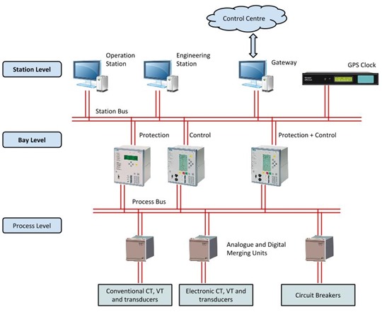
 The image illustrates the concepts associated with a digital substation. In the arrangement, the workstations, protection devices and low level transducers are connected together on an optical fibre communications backbone. The substation system architecture is dividing into three levels; 1) the station level where operations, engineering functions and reporting take place, 2) the bay level where system protection and control functions are implements and 3) the process level where signals from CTs and other transducers are transmitted.
System Architecture
The digital substation starts with IEC 61850 "Communication networks and systems in substations". This is the international standard governing communications, SCADA and automation systems within substations. It is the backbone and framework around which a digital substation is built.
The standard has ten parts, and the structure is summarised by the following:
- Parts 1 to 3 - are an overview and guide to understanding the standard, in addition to providing the general rules.
- Part 4 - project management of products and tenders for an IEC 61850 installation.
- Part 5 and 6 - detail the communication requirements and language used.
- Part 7 - provides details on the data models and transactions used by the standard.
- Parts 8 and 9 - identify the required mappings for the station and process bus.
- Part 10 - provides instruction on how to carry out conformance testing of an IEC 62850 installation.
The digital substation is implemented using the elements and components shown in the illustration. While the arrangement shown in not the only way to implement a digital substation, it does represent one of the more commonly adopted approaches.
By taking the various elements required of a substation (circuit breakers, protection relays, CTs and VTs, etc.) and interconnecting these using optical fibre, the physical realisation of a substation becomes easier while at the same time, it's reliability and understandability increases. Compared to the traditional substation where everything is connected together with hundreds of individual copper cables, the advantages become obvious.
The digital substations consist of several key components and elements.
Intelligent Electronic Devices (IDE)
_thumb.png) IED - REF615 Relay
IED - REF615 Relay Image Source:
ABB The substation primary devices (protection relays, tap-changers, CTs, etc) are implemented as intelligent electronic devices (IED). These devices can communication with each other (and higher level substation control) via the 61850 optical network.
Generic Object Oriented Substation Event (GOOSE)
The 61850 optical network operates using the Ethernet protocol. Within this framework traditional digital signals are transmitted using a generic object-oriented substation event (GOOSE). GOOSE is a specific formatting of data which enable protection status signals to be transmitted in a time period under 4 ms. The is essential to ensure the reliable and timely operation of interconnected IED.
Station and Process Bus
_thumb.png) Compact Industrial Ethernet Switch
Compact Industrial Ethernet Switch Image Source:
RuggedCom These two communication bus allow signals to be exchanged between the bay level IED and station control (station bus) and the bay level IED and system equipment, devices and transducers (process bus).
The above diagram shows dual redundant station and process bus. This provides a greater reliability for important substations as compared to a single bus. The station and process bus systems are typically implemented using Ethernet switches (external or built into the IED), connected together in a ring configuration.
GPS Time Clock
_thumb.png) IEC 61850 GPS Clock
IEC 61850 GPS Clock Image Source:
Tekron An important requirement of the digital substation is the accurate keeping of time. This not only ensures the protection functions operate within the required times, but synchronises substations in different locations so that event and operation logs can be compared and trip events analysed.
The preferred approach to achieving this is by the use of a GPS clock to transmit time synchronisation signals to the IED, using Simple Network Time Protocol (SNTP).
Merging Units
_thumb.png) COSI-MU Merging Unit
COSI-MU Merging Unit Image Source:
Alstom Merging units collect signals for various items of equipment and transducers. This signals are then transmitted via the process bus to other devices. The merging unit is the interface between the traditional analogue signals and the bay controllers and protection relays.
Electronic Fibre Optic CT and VT
_thumb.png) Magneto-Optic Current Transformer
Magneto-Optic Current Transformer Image Source:
ABB A growing trend in the digital substation is the use of optical current and voltage transducers (sometimes called non-conventional instrument transformers - NCIT). These devices operate by measuring changes in the optical performance of fibres in the presence of electric and magnetic fields. The transducers are able to measure both current and voltage.
As the signals are generated and transmitted using optical fibre, transducer signals are not subject to voltage drop issues and electromagnetic interference which can affect conventional equipment. Optical transducers also tend to be smaller, have improved linear characteristics and more accurately reproduce the primary signal.
Note: current measurement uses the Faraday Effect and voltage measurement uses the Pockels Effect.
Advantages of the Digital Substation
The digital substation offers numerous advantages over a conventional arrangement. These include:
- easier and simpler installation (much less wiring)
- interoperability between devices made by different manufacturers
- improved reliability
- improved measurement accuracy and recording of information
- improved commissioning and operations
- easy incorporation of modern electronic CT and VT sensors
- better EMC performance and isolation of circuits
Hope this has given everyone a good overview. If anyone has anything to add, please leave a comment.