Operational Amplifier 

By on

The fundamental component of any analogue computer is the operational amplifier, or op amp. An operational amplifier (often called an op-amp,) is a high-gain electronic voltage amplifier with a differential input and, usually, a single-ended output.

Op-amps are among the most widely used electronic devices today, being used in a vast array of consumer, industrial, and scientific devices. Many standard IC op-amps cost only a few cents in moderate production volume; however some integrated or hybrid operational amplifiers with special performance specifications may cost significantly more.

Operation

Basic Op Amp CircuitThe amplifier's differential inputs consist of a V+ input and a V input, and ideally the op amp amplifies only the difference in [[voltage]] between the two (called the differential input voltage). The output voltage of the op-amp is given by the equation:

myElectrical Equation 

where V+ is the voltage at the non-inverting terminal, V- is the voltage at the inverting terminal and AOL is the open-loop gain of the amplifier.

The magnitude of AOL is typically very large (seldom less than a million) and even a quite small differential input voltage will result in amplifier saturation.

If linear operation is desired, negative feedback must be used and is usually achieved by applying a portion of the output voltage to the inverting input. The feedback enables the output of the amplifier to keep the inputs at or near the same voltage so that saturation does not occur.

Idea Op Amp

An ideal op-amp is would have the following properties. In practice, none of these ideals can be realized, and various shortcomings and compromises have to be accepted.

  • Infinite open-loop gain
  • Infinite voltage range available at the output
  • Infinite bandwidth
  • Infinite input impedance
  • Zero input current
  • Zero input offset voltage
  • Infinite slew rate
  • Zero output impedance
  • Zero noise
  • Infinite common-mode rejection ratio (CMRR)
  • Infinite power supply rejection ratio

Applications

Op-amps are often used in electronic circuit design. The use of op-amps as circuit blocks is generally much easier and clearer than specifying all their individual circuit elements ([[transistors]],[[resistor| resistors]], etc.).

Basic Op 'Amp' Circuits


Circuit Transfer Function
Inverting amplifier
myElectrical Equation
Non-inverting amplifier
myElectrical Equation
Differential input amplifier

myElectrical Equation

with

myElectrical Equation

Adding, Subtracting & Scaling
myElectrical Equation
Voltage follower
myElectrical Equation
Current amplifier

myElectrical Equation
Integrating amplifier
myElectrical Equation
Differentiating amplifier

myElectrical Equation


Voltage Gain of Op-amps

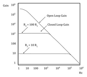
Op Amp Gain
Op-amp Gain

Real op-amp such as the commonly available uA741, do not have infinite gain or bandwidth but have a typical "Open Loop Gain". This is defined as the amplifiers output amplification without any external feedback signals connected to it and for a typical operational amplifier is 105 to 106 at DC (zero Hz). This output gain decreases linearly with frequency down to "Unity Gain" or 1, at about 1MHz.


Steven McFadyen's avatar Steven McFadyen

Steven has over twenty five years experience working on some of the largest construction projects. He has a deep technical understanding of electrical engineering and is keen to share this knowledge. About the author

myElectrical Engineering

comments powered by Disqus

  1. on ap's avatar on ap says:
    10/26/2013 4:59 PM

    I like this page so much. All imformation here help for my work


Comments are closed for this post:
  • have a question or need help, please use our Questions Section
  • spotted an error or have additional info that you think should be in this post, feel free to Contact Us


Low Voltage Switchroom Design Guide

Low voltage (LV) switchrooms are common across all industries and one of the more common spatial requirements which need to be designed into a project...

DC Component of Asymmetrical Faults

The image (reproduced from IEC 60909) shows a typical fault in an ac system.  From the illustration it can seen that there is an initial dc component ...

Wiki Depreciation

We have had the Wiki with us for a long time now, but at last I have decided to say bye bye – more details on why below.

Michael Faraday (the father of electrical engineering)

Famed English chemist and physicist Michael Faraday was born on September 22, 1791, in Newington Butts, a suburb of Surrey just south of the London Bridge...

Calculating Cable Fault Ratings

When selecting a cable, the performance of the cable under fault conditions is an important consideration. It is important that calculations be carried...

IEC 61439 - The Switchgear Standard

The new standard IEC 61439 replaces the old 60439. Compared to the old standard, the new 61439 is a more clearly defined and takes into account the assembly...

Random Numbers

Using laser optical pulses the random number generator utilizes the time between arrival of random photos to generate the numbers, ensuring true accuracy...

How to Size Current Transformers

The correct sizing of current transformers is required to ensure satisfactory operation of measuring instruments and protection relays. Several methods...

Cable Sizing Software

When sizing cables nearly, everyone uses some form of software. This ranges from homespun spreadsheets to complex network analyses software. Each has its...

UPS Battery Sizing

Various techniques exist to enable the correct selection of batteries for UPS applications.  The procedure described below is one of the more common. ...

Have some knowledge to share

If you have some expert knowledge or experience, why not consider sharing this with our community.  

By writing an electrical note, you will be educating our users and at the same time promoting your expertise within the engineering community.

To get started and understand our policy, you can read our How to Write an Electrical Note