How to Size Current Transformers
The correct sizing of current transformers is required to ensure satisfactory operation of measuring instruments and protection relays. Several methods exist to size current transformers. This note will look at several methods, with particular attention being paid to protection class CTs sized in IEC 60044, which is adopted internationally.

ABB Current
Transformer Example of a CT specification: - a very common specification for a protection class CT would be an accuracy class 5P (1%), with rated accuracy limiting factors of 10 or 20. Typical burdens would be 5, 10, 15 or 20 VA. A typical specification would be 5P10 15 VA.
The IEC 60044 Method
IEC 60044 specifies the requirements for protection CTs (in addition to measuring CT's, VTs and electronic sensors).
The key to CT dimensioning under the standard, is the symmetrical short circuit current and transient dimensioning factors:
- Kssc - rated symmetrical short-circuit current factor
- K’ssc - effective symmetrical short-circuit current factor
- Ktd - transient dimensioning factor
Example IEC 60044 Calculation
Consider a CT with the following specification and protection requirements:
- CT: 600/1 5P20 15 VA, Rct = 4 Ω
- CT Leads: 6 mm2, 50 m long
- use R=2 ρ l /a to calculate = 0.0179 Ω/m - Relay: Siemens 7SJ45, Ktd = 1
- Short circuit current, Iscc max = 30 kA
To find the lead resistance Rleads (two leads – supply, return) we can use the standard formulae for resistivity:
Rleads = 2 ρ l /a = 2 x 0.0175 x 50 / 6 = 0.3 Ω
Numerical relays have low burdens, typically 0.1 Ω (where possible the relay manual should be consulted).
Plugging everything into the equations:
Rb = 15 VA / 1 A2 = 15 Ω
R’b = Rleads + Rrelay = 0.3 + 0.1 = 0.4 Ω
K’scc = Kscc (Rct + Rb)/(Rct + R’b)
= 20 (4 + 15 )/ (4 + 0.4) = 86.4
Required K’scc > 1 x 30000/600 = 50
In this case the effective K’scc of 86.4 is greater than the required K’scc of 50 and the CT meets the stability criteria.
The factor
Kssc is relatively easy to understand and relates to the liner portion of a CT characteristic. The voltage and current across a CT are linear only up till a certain value (normally specified as a multiple of the nominal rating), after which the CT will saturate and the curve will level off. A CT rated at say 5P20 will stay linear to approximately 20 times its nominal current. This linear limit is the K
ssc (i.e. K
ssc = 20). As a reminder, the 5 [in the 5P20] would be the CT accuracy class and the ‘P’ signifies a protection class CT.
Slightly more complicated is the effective factor, K’scc. This is a calculated value which takes into account the burden (resistance) of the relay, resistance of the CT windings and resistance of the leads:

- Rct - secondary winding d.c. resistance at specified temperature
- Rb - rated resistive burden of the relay
- R’b - Rleads + Rrelay; this is thel connected burden
CTs need to be able to supply the required current to drive the relays during transient fault conditions. The ability of the CT and relay to operate under these conditions is a function of K’scc and the transient performance of the relay, Ktd. The factor, Ktd is supplied by the relay manufacturer. Correct functioning is achieved by ensuring the following is valid:

That it. Once you have confirmed the above is ok, you know your CT is ok.
What the Manufacturer Wants
There is a slight complication in the manufacturers know their relays better than we (or the IEC) do. As general advice, you should always refer to the manufacturers information:
- firstly it is the only way to get the factor Ktd
- secondly manufacturers sometimes have additional requirements; for example Siemens’ overcurrent, motor protection, line differential (non-pilot)and transformer differential are good to go with the above, while their line differential (pilot wire) and distance relays require the above and have additional limitations on K’scc
Connection Leads
In the sizing of protection transformers, the resistance (burden) of the connection leads can have a considerable effect. In calculations, the resistance of the connection leads can be estimated from:

where:
l is the connection lead length in m
ρ is the resistivity in Ω mm2 m-1 (=0.0179 for copper)
A is the cross sectional area in mm2
Other CT Sizing Methods and Requirements
BS 3938 and BS 7626
BS 3938 and BS 7626 are older British Standards which deal the the specification and sizing of current transformers. Both of these have been withdrawn and are superseded by the IEC 6044 standard.
The standards adopted the concept of knee voltage and it is still common to find knee voltage voltage being used as a CT sizing parameter.
Knee voltage is defined as the point at which a 10% increase in voltage across the terminals, causes a 50% increase in excitation current
Utilising the British Standards, CTs were defined by the knee point voltage UKN and the internal secondary resistance Ri. To convert an IEC design the following can be used:
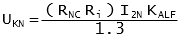
where: I2N is the nominal secondary current
ANSI/IEEE C57.13
The IEEE standard C57.13 covers the requirements for CT sizing in the North American markets.
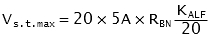
Class C of the standard defines CTs by their secondary terminal voltage at 20 times nominal current (for which the ratio error shall not exceed 10%). Standard classes are C100, C200, C400 and C800 for 5 A nominal secondary current.
This terminal voltage can be calculated from the IEC data as follows:
with 
and 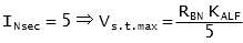
If anyone has any questions, comments or suggestions on how to improve the post, please add them below.