Inductance 

By on

When current flows within a wire, a magnetic field is created. The potion of this magnetic field perpendicular to the wire is called the magnetic flux (measured in weber, Wb). Inductance is the ratio of magnetic flux to current in a circuit. The unit of inductance is the henry, H (Wb/A) and is normally represented by the symbol L.

Self Inductance

Whenever current in a coil of wire changes,  the magnetic field]it produces will change. That will change the magnetic flux through the coil and hence produce a voltage across the coil. This is called self-inductance, and the coil is referred to as an inductor.

Example – Self Inductance of a Solenoid

Consider a coil of wire around a magnetic core, whose length is much greater than it's diameter. 

Given the permeability of free space μo , relative permeability of the magnetic core μr , number of turns N and length of solenoid l, with a current i flowing, the magnetic flux density, B within the coil is is given by:

image00

The magnetic flux, Φ is obtained by multiplying flux density by the cross sectional area A:

image01

Given that the inductance is the ratio of magnetic flux to current, we have:

image02

Note: if the solenoid is wound around a non-magnetic core, then μr = 1.

Mutual Inductance

When the magnetic field of one coil links with that of another coil, a change in current in the first coil will produce a linking magnetic field with the second coil.  The magnetic field linking with the second coil will produce a voltage within that coil.  This is called mutual inductance.

For two inductors (coils) we have:

  • L11 – self inductance of inductor 1
  • L22 – self inductance of inductor 2
  • L12 = L21 – mutual inductance between the two

Inductance Formulae

The table below lists some common formulae for calculating the theoretical inductance of several inductor constructions.

  • L = inductance (H)
  • μ0 = permeability of free space = 4 π× 10-7 (H/m)
  • μr = relative permeability of core material

Cylindrical coil:

myElectrical Equation N = number of turns
A = area of cross-section of the coil in square metres (m2)
l = length of coil in metres (m)


Straight wire conductor:

myElectrical Equation 
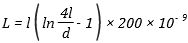
l = length of conductor (m)
d = diameter of conductor (m)


Flat spiral air-core coil:

myElectrical Equation 
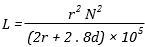
r = mean radius of coil (m)
N = number of turns
d = depth of coil (outer radius minus inner radius) (m)

Toroidal core, circular cross-section:
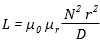
myElectrical Equation N = number of turns
r = radius of coil winding (m)
D = overall diameter of toroid (m)

Application to Circuits

The quantitative measure of applying an inductance L, to a circuit defined by:

myElectrical Equation

An inductor can store energy. The power (= energy / time) being stored in an inductor is:

myElectrical Equation

This implies (by a little calculus) that the energy stored in an inductor is :

myElectrical Equation


Steven McFadyen's avatar Steven McFadyen

Steven has over twenty five years experience working on some of the largest construction projects. He has a deep technical understanding of electrical engineering and is keen to share this knowledge. About the author

myElectrical Engineering

comments powered by Disqus

  1. Chris's avatar Chris says:
    7/12/2012 3:52 AM

    You list the relative permeability of non-magnetic materials as 0. Shouldn't it be 1?

    • Steven's avatar Steven says:
      7/14/2012 9:45 AM

      Thanks for spotting the error Chris. I have corrected it.


Comments are closed for this post:
  • have a question or need help, please use our Questions Section
  • spotted an error or have additional info that you think should be in this post, feel free to Contact Us


Why is electricity so hard to understand?

It's been a busy few months on different projects or busy couple of decades depending on how I look at it. I can say that on the odd (frequent) occasion...

How D.C. to A.C. Inverters Work

Traditionally generation of electricity has involved rotating machines to produce alternating sinusoidal voltage and current (a.c. systems). With the development...

Motor Efficiency Classification

Electric motors are one of the most widely used items of electrical equipment. Improving motor efficiency benefits include, reduced power demand, lower...

Photovoltaic (PV) - Utility Power Grid Interface

Photovoltaic (PV) systems are typically more efficient when connected in parallel with a main power gird. During periods when the PV system generates energy...

Cables for MV Power Distribution - Earthed versus Unearthed Systems

Power cables can basically be classified into earthed and unearthed cables, where earthed and unearthed refer to the application for which the cable is...

Medium Voltage Switchgear Room Design Guide

Many medium voltage (MV) indoor switchgear rooms  exist worldwide. The complexity of these rooms varies considerably depending on location, function and...

9 power supply issues solved by using a UPS

Installation of a UPS can help in reducing problems due to issues with the power supply.  A lot of people relate this to nine key issues.  Depending on...

What is LED?

Light Emitting Diodes (LED ) are increasing gaining favour in both the domestic and commercial sectors; due to their efficiency, sustainability and durability...

Copyright Infringement

myElectrical does not support or promote the use of copyrighted material without the copyright owner's consent. If you believe that material for which...

Maxwell's Equations - Gauss's Electric Field Law

Gauss's Electrical law defines the relation between charge ("Positive" & "Negative") and electric field.  The law was initially formulated by Carl Friedrich...

Have some knowledge to share

If you have some expert knowledge or experience, why not consider sharing this with our community.  

By writing an electrical note, you will be educating our users and at the same time promoting your expertise within the engineering community.

To get started and understand our policy, you can read our How to Write an Electrical Note