Difference Between Live and Dead Tank Circuit Breakers 

By on


Siemens Dead Tank Circuit Breaker
A quick post in connection with an email question:

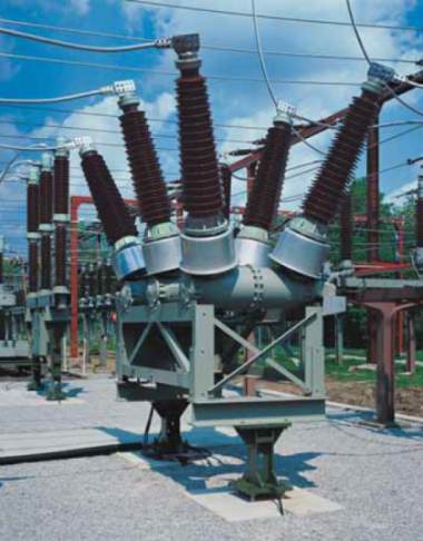
Live Tank -  the circuit breaker the switching unit is located in an insulator bushing which is live at line voltage (or some voltage above ground). Live Tank circuit breakers are cheaper than dead tank and require less space.

Dead Tank -  the switching unit is located within a metallic container which is kept a earth potential.  As the incoming/outgoing conductors are taken through insulated bushings, it is possible to place current transformers on these (with a Live Tank arrangement this is not possible and separate CTs are required). 

The terms Live and Dead Tank normally only apply to high voltage circuit breakers


Steven McFadyen's avatar Steven McFadyen

Steven has over twenty five years experience working on some of the largest construction projects. He has a deep technical understanding of electrical engineering and is keen to share this knowledge. About the author

myElectrical Engineering

comments powered by Disqus

  1. tang's avatar tang says:
    8/23/2012 8:15 AM

    What is the ground clearance for dead tank CT?

    • Steven's avatar Steven says:
      8/26/2012 12:17 PM

      With a dead tank circuit breaker, the CT primary side is still isolated, so I'm not sure about why you are worried with ground clearance.


Comments are closed for this post:
  • have a question or need help, please use our Questions Section
  • spotted an error or have additional info that you think should be in this post, feel free to Contact Us


How to Write an Electrical Note

Electrical notes are a collaborative collection of electrical engineering information and educational material. Any registered user can add content. ...

Why a Sine Wave?

I received this question by email a few weeks. First thoughts was that it is a product of the mathematics of rotating a straight conductor in a magnetic...

Cable Sheath and Armour Loss

When sizing cables, the heat generated  by losses within any sheath or armour need to be evaluated. When significant, it becomes a factor to be considered...

Load Flow Study – how they work

A load flow study is the analysis of an electrical network carried out by an electrical engineer. The purpose is to understand how power flows around...

Introduction to Current Transformers

Current transformers (CTs) are used to convert high level currents to a smaller more reasonable level for use as inputs to protection relays and metering...

Material Properties

Everything physical in electrical engineering from insulations to conductors revolves around materials. Here we are listing common materials along with...

Induction Motor Calculator

Just added a page to the tools, which will allow you to calculate the synchronous speed, slip and rated torque for an induction motor. Not a particularly...

Microsoft OneNote

A couple of months ago I came Microsoft's OneNote and downloaded the 60 day free trail. Since then I have been using it regularly and now have a full license...

Low Voltage Switchroom Design Guide

Low voltage (LV) switchrooms are common across all industries and one of the more common spatial requirements which need to be designed into a project...

How D.C. to A.C. Inverters Work

Traditionally generation of electricity has involved rotating machines to produce alternating sinusoidal voltage and current (a.c. systems). With the development...

Have some knowledge to share

If you have some expert knowledge or experience, why not consider sharing this with our community.  

By writing an electrical note, you will be educating our users and at the same time promoting your expertise within the engineering community.

To get started and understand our policy, you can read our How to Write an Electrical Note