Switchboard - Forms of Internal Separation 

By on

IEC 61439 'Low-voltage switchgear and controlgear assemblies', specifies standard arrangements of switchboard (call forms of internal separation).

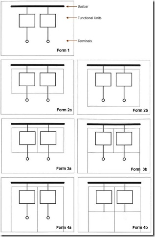
The are labelled as Form 1, Form 2, Form 3 and Form 4. Forms 2, 3 and 4 are further broken down into Form 2a, 2b, 3a, 3b, 4a and 4b.

Each Form relates to the internal separation of the busbars, functional units and terminals, each being defined as:

  • Busbar - low impedance conductor to which several electric circuits can be connected
    • Main busbar - busbar to which one or more distribution busbar, incoming unit or outgoing unit can be connected

    • Distribution busbar - busbar in one section which is connected to the main busbar from which incoming or outgoing units can be connected

  • Functional Unit - part of the assembly comprising the electrical and mechanical elements that contribute to the fulfilment of the same function

    • Incoming unit - functional unit which feeds energy into the assembly

    • Outgoing unit - functional unit supplying energy to the outgoing circuits

  • Terminals - part of the assembly which provide for connection of incoming and outgoing cable and busbar

Internal separation is achieved by the use of barriers or partitions (including metallic or non-metallic), insulation of live parts or an integral housing (i.e. moulded case circuit breaker). The internal barriers should provide protection against contact to IP XXB and against the ingress of foreign bodies to at least IP 2X.

Form 1 has no internal separation between , while Form 4b has the greatest with busbars, functional units and terminals all being separated (see illustration):

  • IEC61439FormsOfSeperation
    Forms of separation
    Form 1
    - no internal separation of the busbars, functional units and terminals from each other.
  • Form 2a - separation of the busbars from the functional units. Terminals are not separated from the busbars.
  • Form 2b - as for 2a, but with the terminals are not separated from the functional units.
  • Form 3a - separation of the busbars from the functional units and each functional unit from the other units. Terminals of each functional unit are not separated from each other. Terminals are not separate from the busbars.
  • Form 3b - as per 3a, but with the terminals separated from the busbar (and functional units)
  • Form 4a - separation of the busbars from the functional units and each functional unit from the other units. Separation of the terminals for a functional unit from the busbars and those of any other unit. Terminals enclosed in the same compartment as the functional unit.
  • Form 4b - as per 4a, but with the terminals for each functional unit enclosed in their own space.

BS EN National Annex

The United Kingdom implementation of the IEC standard (in BS EN 61439-2) further defines the separation of busbars and cables by the use of Types.  These have been widely adopted within and outside the United Kingdom.

Form Type Construction
1    
2a    
2b 1

busbars separation is by an insulated covering (i.e. sleeving, wrapping, coatings, etc.)

  2

busbars separated by rigid metallic or non-metallic barriers or partitions

3a    
3b 1

busbars separation is by an insulated covering (i.e. sleeving, wrapping, coatings, etc.)

  2

busbars separated by rigid metallic or non-metallic barriers or partitions

4a 1

busbars separation is by an insulated covering (i.e. sleeving, wrapping, coatings, etc.)
cables may be glanded elsewhere

  2

busbars separated by rigid metallic or non-metallic barriers or partitions
cables may be glanded elsewhere

  3

busbars separated by rigid metallic or non-metallic barriers or partitions
functional units have integral glanding facilities

4b 4

busbars separation is by an insulated covering (i.e. sleeving, wrapping, coatings, etc.)
cables may be glanded elsewhere

  5

busbars separated by rigid metallic or non-metallic barriers or partitions
terminals separated by insulated covering, glanded in common cable chamber

  6

all separation requirements by rigid metallic or non-metallic barriers or partitions
glanded in common cable chamber

  7

all separation requirements by rigid metallic or non-metallic barriers or partitions
functional units have integral glanding facilities


You may also be interested in the related post IEC 61439 Verification Methods.


Steven McFadyen's avatar Steven McFadyen

Steven has over twenty five years experience working on some of the largest construction projects. He has a deep technical understanding of electrical engineering and is keen to share this knowledge. About the author

myElectrical Engineering

comments powered by Disqus

  1. naban's avatar naban says:
    2/3/2012 3:50 PM

    Please describe "type testing" of switchboards and how it is done and guidelines,codes,requirements(test voltage,leakage current etc) of a good switchboard etc. Should the testing be done before making the complete switchboard including or afterwards?.

    • Steven's avatar Steven says:
      2/4/2012 9:47 AM

      Naban,
      Thanks for the comment. If you need a quick answer, testing of switchboard assemblies is fully detailed in the IEC 61439 standard. If you can wait a bit, I have added this to my lists of future posts and will get round to writing a post on it at some stage.

    • Steven's avatar Steven says:
      2/20/2012 8:17 AM

      As promised, I have added a post on IEC 61439 verficiation:
      IEC 61439 Verification Methods

  2. Peter's avatar Peter says:
    2/15/2012 8:02 AM

    What about types – Form 4B Type 5 for example?

    • Steven's avatar Steven says:
      2/15/2012 9:49 AM

      Peter, thanks for the question.

      Types are not part of the IEC standard, but are specific to the British (BS EN standard). BS EN 61439 (and most other BS EN standards) are copies of the same numbered IEC standard, with a National Annex at the back. The National Annex lists deviations/additions to the IEC standard which are specifically applicable to the UK.

      The National Annex for BS EN 61439 details with Types of switchboard. For your example the Form 4b Type 5 is listed as requiring ‘Busbar separation is by metallic or nonmetallic rigid barriers or partitions. Terminals may be separated by insulated coverings and glanded in common cabling chamber(s)’. For the other types associated with each form, you need to look at the standard.

    • Peter's avatar Peter says:
      2/15/2012 11:37 AM

      Thanks for the quick reply Steven. All clear.

  3. Opinion's avatar Opinion says:
    3/24/2012 3:44 PM

    Trackback from Opinion

    The (relatively new) switchgear and control gear standard, IEC 61439 'Low-voltage switchgear and controlgear assemblies' has three methods which can be used to verify the characteristics of an assembly will meet the standard. These are verification b ...

  4. comet47's avatar comet47 says:
    6/14/2012 3:42 PM

    Form 4 Type 7 as shown on the guides is misleading I feel in some respects.
    Whilst the requirement is to gland at the outgoing unit it is often difficult to terminate large armoured cables at this point in a board.
    In my opinion it is still satisfactory to gland the armouring in a SWA gland at the roof or floor and continue to the inner box where a Pg gland can be fitted. This allows for easier glanding of heavy cables and prevent ingress to the board of small creatures which could pass through IP2x gaps in the cable compartment.
    However I have met clients who refuse to accept such a solution.
    Any comments on this

    • Steven's avatar Steven says:
      6/19/2012 7:43 AM

      Type 7 is from the national annex for the UK implementation of the IEC standard and requires integral glanding in for each termination. Types 1 to 6 are more open and probably do accommodate the scenario you are presenting.

      The specification of type is by the electrical designers. Why engineers choose Type 7 could be different – maybe they have some technical requirement, it could be a requirement from a local authority, just something they have always done or maybe just because it is the most stringent.

      From my experience, I ‘m not sure how often people really consider the selection of most appropriate Form and Type. Ideally we should be looking at the technical performance, cost, practicalities of installation, operational and maintenance requirements, etc. – the correct selection is something of a trade off.


Comments are closed for this post:
  • have a question or need help, please use our Questions Section
  • spotted an error or have additional info that you think should be in this post, feel free to Contact Us


Network Theory – Introduction and Review

In electrical engineering, Network Theory is the study of how to solve circuit problems. By analyzing circuits, the engineer looks to determine the various...

What is Aircraft Ground Power

Ever wondered what kind of power an aircraft uses when parked at the airport stand. Normally the aircraft generates it own power, but when parked with...

8 Steps to Low Voltage Power Cable Selection and Sizing

A recurring theme on our forums is cable sizing. Now many installations are unique and require special consideration. However, a lot of the time things...

How a Digital Substation Works

Traditionally substations have used circuit breakers, current transformers (CT), voltage transformers (VT) and protection relays all wired together using...

How to Calculate Motor Starting Time

Request to look at induction motor starting time have come up a few times on the site. Hopefully in this post, I give you guys some idea on how to calculate...

Low Voltage Switchroom Design Guide

Low voltage (LV) switchrooms are common across all industries and one of the more common spatial requirements which need to be designed into a project...

Batteries

A battery consists of one or more cells, each of which use stored chemical energy to produce electrical energy, There are many types of cells and these...

The ac resistance of conductors

In a previous article I looked at the dc resistance of conductors and in this article we turn our attention to ac resistance. If you have not read the...

Capacitors - Energy Storage Application

Capacitors have numerous applications in electrical and electronic applications.  This note examines the use of capacitors to store electrical energy....

Dielectric loss in cables

Dielectrics (insulating materials for example) when subjected to a varying electric field, will have some energy loss.   The varying electric field causes...

Have some knowledge to share

If you have some expert knowledge or experience, why not consider sharing this with our community.  

By writing an electrical note, you will be educating our users and at the same time promoting your expertise within the engineering community.

To get started and understand our policy, you can read our How to Write an Electrical Note