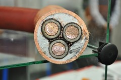
Dielectric loss in cables
 Cable cross section showing
insulation
Dielectrics (insulating materials for example) when subjected to a varying electric field, will have some energy loss. The varying electric field causes
small realignment of weakly bonded molecules, which lead to the production of heat. The
amount of loss increases as the voltage level is increased. For low voltage cables, the loss is usually insignificant and is generally ignored. For higher voltage cables, the loss and heat generated can become important and needs to be taken into consideration.
Dielectrics (insulating materials for example) when subjected to a varying electric field, will have some energy loss. The varying electric field causes small realignment of weakly bonded molecules, which lead to the production of heat. The amount of loss increases as the voltage level is increased. For low voltage cables, the loss is usually insignificant and is generally ignored. For higher voltage cables, the loss and heat generated can become important and needs to be taken into consideration.
Dielectric loss is measured using what is known as the loss tangent or tan delta (tan δ). In simple terms, tan delta is the tangent of the angle between the alternating field vector and the loss component of the material. The higher the value of tan δ the greater the dielectric loss will be. For a list of tan δ values for different insulating material, please see the Cable Insulation Properties note.
Note: in d.c. cables with a static electric field, there is no dielectric loss. Hence the consideration of dielectric loss only applies to a.c. cables.
Cable Voltage
Dielectric loss only really become significant and needs to be taken into account at higher voltages. IEC 60287 "Electric Cables - Calculation of the current rating", suggests that dielectric loss need only be considered for cables above the following voltage levels:
| Cable Type |
U0, kV |
| Butyl Rubber |
18 |
| EDR |
63.5 |
| Impregnated Paper (oil or gas-filled) |
63.5 |
| Impregnated Paper (solid) |
38 |
| PE (high and low density) |
127 |
| PVC |
6 |
| XLPE (filled) |
63.5 |
| XLPE (unfilled) |
127 |
Cable Dielectric Loss
Cable Capacitance
Cable capacitance can be obtained from manufacturers or for circular conductors calculated using the following:
Given the tan δ and capacitance of the cable, the dielectric loss is easily calculated:
It is possible to use the above for other conductor shapes if the geometric mean is substituted for Di and dc.
Symbols
dc - diameter of conductor, mm
Di - external diameter of insulation, mm
C - cable capacitance per unit length, F.m-1
U0 - cable rated voltage to earth, V
Wd - dielectric loss per unit length, W.m-1
tan δ - loss factor for insulation
ε - insulation relative permitivity
ω - angular frequency (2πf)
See Also