Medium Voltage Switchgear Room Design Guide
Many medium voltage (MV) indoor switchgear rooms exist worldwide. The complexity of these rooms varies considerably depending on location, function and technology adopted by the owner. This article provides general guidance on the factors to be considered in the design of a typical room.
Typical Switchroom Equipment
Switchboards
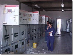
 The positioning of indoor MV switchboards requires careful consideration. Suitable access around the switchboard for maintenance, withdrawing of circuit breakers, safety and regulatory compliance needs to be allowed. Under fault conditions many switchgear require a minimum clear space above for the venting of gases. Attention needs to be given to the fixing down of switchboards and cable entry into and out of the switchboards.
Protection Panels
While relays can be incorporated within the switchboards, often they are installed in separate panels/racks. Provision needs to be made for the installation of any protection panels and control cabling to the associated switchboards.
Auxiliary Systems & Other Considerations
In addition to major equipment, there is whole host of other systems and issues which need to be considered in the design of any given installation:
Earthing & Lightning Protection - given the high levels of fault current associated with MV switchrooms, consideration of the earthing (grounding) is an important aspect of the design. Earthing systems need to provide adequate paths for fault current, ensure sufficient current for relay operation and limit step and touch potentials to safe values. Lightning protection if necessary needs to be installed and coordinated with the earthing system to provide a safe means to discharge any strike to ground.
SCADA - modern relays, switchgear and automation rely heavily on SCADA systems for operation and engineering access. These can become quite significant requiring equipment racks and associated cable distribution.
DC Systems – protection relays often work with dc supplies. Space provision for suitable dc supplies (rectifier, controls, batteries, etc.) needs to be considered in developing the switchroom layout.
Cable Containment – power MV cabling, low voltage cabling, control and SCADA cabling and optical fibres all require to be routed between equipment as well as into and out of the building. This can require significant space in terms of cable ladders and trenching. In many installation basement or below floor space is utilised for cable containment.
Building Services - whilst the purpose of the switchroom is to hold the MV equipment, building services (lighting, small power, fire detection and protection, ventilation and air-conditioning, security and access control all need to be considered and provided where appropriate. To provide the building services an external low voltage supply will be required.
EMF - there is a growing concern over the effect of EMF on the human body. Where people have access to areas surrounding switchrooms cable distribution paths it is necessary to establish that the associated EMF levels are below recommended limits.
Switchroom Layout
Switchrooms are built to house switchgear and associated systems (cables, dc systems, SCADA and cable containment). Suitable provision should be made within the room for all these systems. In addition requirements such as toilets, desks, telephones, security systems, etc. may need to be considered.
Much of the equipment located within the switchroom is large and heavy. Suitable provision should be made for access to the switchroom, entrance into the room and moving the equipment around. Installation and removal of individual items of equipment should be possible with the switchroom live. Care needs to be taken around columns and other obstructions to ensure that clearance distances are maintained.
It is good practice (and a regulatory requirement in many countries) to provide at least two means of emergency egress. Doors providing emergency egress should open outwards.
Entry/exit to the building needs to be considered carefully to ensure suitable access and that water does not leak/enter the room.
Switchgear Room Dimensioning
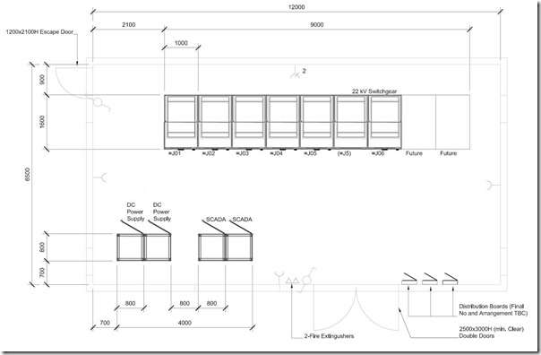
Each switchroom is unique and needs to be considered in relation to the specific equipment which will be installed. As an illustration, the diagram below shows simple room layout consisting of a 22 kV switchboard, some DC and SCADA panels (click for a larger image).

The layout illustrates some of the key dimensions and issues to be considered:
Circuits – the room has been designed for a 22 kV system of five circuits and a bus-coupler, give a total of seven panels (two for the bus-coupler). Depending on actual number of circuits the room width can be easily expanded or reduced. Provision has also been made for the installation of future panels.
Switchboard Size – the arrangement is based on 600x1000mm panels. Should the actual panels be larger the necessary adjustments would have to be made.
Clearances – minimum statutory clearances always need to be observed. In addition to statutory limits, the designer needs to ensure there is adequate clearance for operational and maintenance requirements – often these would be larger than statuary minimums.
Front Entry – the scheme shown allows for access to the rear of the switchboard. Should the switchboard require only front access, the rear space could be reduced (to say 100 mm, just keeping the switchboard from the wall).
Height – sufficient height needs to be allowed to ensure adequate movement and operation of the switchboards. In practice, a height of 3700 mm is typical. Depending on type of switchboard this may need to be increased to allow for the exhaust of arc gasses during fault conditions.
Not shown on the example is lighting and air-conditioning systems. Given a room height of 3700 mm and space shown as the front of the layout, there is sufficient space to easily accommodate these.
See Also