Voltage Drop in Installations - Concepts 

By on

Problems on achieving maximum voltage drop within an installation come up often.  Depending where you live, local regulations will have different limits on maximum allowable voltage drop, however the intent of all of these is to ensure sufficient voltage is available at the equipment so that if functions correctly.  Specified voltage drops are generally not for an individual cable but for the full installation;  from the point of supply connection to the final equipment.  Thus the overall voltage drop is a combination of individual voltage drops across multiple cables.

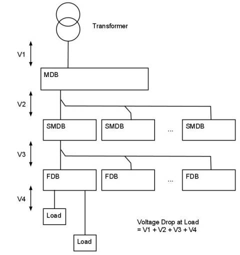
The figure shows a typical installation.  A transformer feeds a main distribution board (MDB), which in turn feeds one or more sub main distribution board (SMDB).  Each SMDB feeds one or more final distribution board (FDB), which in turn supplies the connected equipment.   It is apparent that the total voltage drop at the final equipment is the sum of following voltage drops:

  • Voltage drop (V1) in the cable from the transformer to the MDB (which is carrying the current for all the loads on the system)
  • Voltage drop (V2) in the cable from the MDB to the SMDB (which is carrying the current for all loads in all FDB connected to the SMDB)
  • Voltage drop (V3) in the cable from the SMDB to the FDB (which is carrying the current for all loads connected to the FDB)
  • Voltage drop (V4) in the cable from the FDB to the load (which is carrying the current for the load only)

What becomes obvious is that the voltage drop is a function of the overall system and not trivial to calculate; particularly for a large system.  In order to accurately determine the voltage drop to any load, a complete understanding of the system is required.  Due to this, design is often carried out using computer software which can quickly evaluate the full system and provide a verifiable solution. 

Consideration of a common problem where the voltage drop exceeds the allowable, may help illustrate some of the issues likely to be encountered.  Given a voltage drop which is too larger, this could potentially be resolved by increasing the size of the cable from the FDB to the load.  Increasing this cable may work or could possibly result in a cable which is too large to be practical.  An alternative would be to consider increasing the size of one or more of the cables in the upstream circuits, with the possible benefit of reducing cable sizes on multiple other circuits downstream of this. 

Voltage drop  and the installation cabling system are integrated and tied together.   The example illustrates that consideration of the voltage drop requires a full understanding of the system.   Other aspects of the design complicated this further.  These include consideration of the cost of the installation, system losses and carbon footprint.  By minimizing the amount of copper [cable] used these aspects are reduced, but this needs to be tied in with achieving satiable voltage drops.  Attempting to address all these aspects with numerous combinations of different cables and what-if type scenarios can only be realistically addressed by using some sort of computer program.


Steven McFadyen's avatar Steven McFadyen

Steven has over twenty five years experience working on some of the largest construction projects. He has a deep technical understanding of electrical engineering and is keen to share this knowledge. About the author

myElectrical Engineering

comments powered by Disqus

  1. Sinnadurai's avatar Sinnadurai says:
    10/12/2011 6:30 AM

    Please give acceptable(maximum) voltage drops in lighting circuits and during motor starting and duration. Also give maximum VD and duration allowable at generator terminals during starting large motors

    • Steven's avatar Steven says:
      10/19/2011 1:12 PM

      Allowable voltage drops for lighting circuits varies depending on country. A common figure in some countries I have worked is 4% or 5%. In the UK it is 3% if supplied from a public LV system and 8% if from a private LV system.

      In most buildings motors are relatively small and if the electrical system is correctly designed should not have an effect on the lighting. If the motors are large and/or the system poorly designed then voltage dips could affect the lighting. Offhand I can’t give further general guidance and would need to do a little research and look at voltage variations allowed by the manufacturing standards. Maybe someone else who has had recent experiences of motor starting affecting lighting will share them here.

    • terry dublin's avatar terry dublin says:
      12/1/2011 8:38 PM

      In the UK and Ireland there are different volt drop values for different installation types, i.e. the millivolt/amp/metre for single phase AC 50Hz cables in conduit is different than that for the same cables lying flat on cable tray.
      Why?

  2. Steven's avatar Steven says:
    12/2/2011 9:17 AM

    Not being party to how they arrived at the table, this is assumption but I would guess two reasons - minor variations in resistance and larger variations in reactance (inductance).

    ac resistance - the dc resistance should be the same in all cases. For ac there is skin effect which they may have included. This does depend on the geometric arrangements of conductors and would explain the variations in resistance. It is an interesting topic and at some stage I'll do a post on calculating ac resistance taking into account skin effect.

    reactance (inductance) - this is very much dependant on the geometry of the cable arrangements. As you move cables apart the inductance will increase, change their geometric relationship to each other the inductance will change, etc.

    Note: the mV/A/m is really mΩ/m so we are talking about impedance.

  3. Johnson's avatar Johnson says:
    10/4/2012 6:26 PM

    I need a simplifyed calculation of voltage drop in relation to wiring of premises.


Comments are closed for this post:
  • have a question or need help, please use our Questions Section
  • spotted an error or have additional info that you think should be in this post, feel free to Contact Us


Cost Performance and Time

Often us engineers get so bogged down in equations, using software, producing drawings and writing specifications that this becomes the sole focus.   ...

8 Steps to Low Voltage Power Cable Selection and Sizing

A recurring theme on our forums is cable sizing. Now many installations are unique and require special consideration. However, a lot of the time things...

Electromagnetic Compatibility (EMC)

Electromagnetic compatibility (EMC) is the study of coordinating electromagnetic fields give off equipment, with the withstand (compatibility) of other...

Capacitors - Energy Storage Application

Capacitors have numerous applications in electrical and electronic applications.  This note examines the use of capacitors to store electrical energy....

Paternoster Lifts

These lifts were first built in 1884 by J. E. Hall and called a paternoster ("Our Father", the first two words of the Lord's Prayer in Latin) due to its...

110 or 230 Volts

I've been considering a blog on the 110 or 230 Volt issue for a while.  While browsing the Internet I came across a great summary by Borat over at  engineering...

New Mail Chimp

We've been sending out Newsletters on a regular basis for a few weeks now. To do this we have been using Google's Feedburner service. While Feedburner...

Write your best report

Years ago I was told that you should always try to write the best report you can.  Many years later I still think on this as one of the better pieces of...

Robotics - Home Innovations

We have a sister note to this (Robots - Interesting Video), in which I have posted some videos of interesting robots developed by commercial corporations...

Bows and Arrows

It starts with me reading one of the Horrible History books with my son (Groovy Greeks). Arrows were mentioned which lead to the discussion of the bodkin...

Have some knowledge to share

If you have some expert knowledge or experience, why not consider sharing this with our community.  

By writing an electrical note, you will be educating our users and at the same time promoting your expertise within the engineering community.

To get started and understand our policy, you can read our How to Write an Electrical Note