Resistors 

By on

Resistors
Resistors
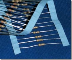
Resistors are electronic components that oppose the flow of current. Manufactured in various types and ranges they have a wide application to electronics.

The relationship between voltage and current in a resistor is given by Ohm's Law:

 myElectrical Equation


Identification and Values

Colour Code

When inspecting resistors, the given value is either printed on the body is can be determined from the resistor colour code.

Resistor Colour Code
Example

ResistorCode

Red(2)Blue(6)Green(5)
=2600000
=2.6 MΩ

The first two bands are the value and the third band is a decimal multiplier (10x).

Black Brown Red Orange Yellow Green Blue Violet Grey White

0

1

2

3

4

5

6

7

8

9


The fourth band give the tolerance:

Gold Silver None

5%

10%

20%

For precision resistors, sometimes a five band colour coding is used – first three bands are the value, fourth band is the multiplier and the fifth band is the tolerance.

Preferred Values

Resistors are manufactured and specified in a range of preferred values. 

The table shows the range of preferred values:

10 12 15 18 22 27 33 39 47 56 68 82

Note: to obtain full range, multiply table by 10X

Circuit Arrangements

For more information on circuit arrangements and how to work these out, please see the following note:


Steven McFadyen's avatar Steven McFadyen

Steven has over twenty five years experience working on some of the largest construction projects. He has a deep technical understanding of electrical engineering and is keen to share this knowledge. About the author

myElectrical Engineering

comments powered by Disqus

  1. resistor's avatar resistor says:
    8/7/2012 7:58 PM

    There also exist 6 band resistors, where the 6th band often refers to the thermal coefficient. for more information on resistor color codes http://www.resistorguide.com/resistor-color-code

    • Steven's avatar Steven says:
      8/8/2012 12:59 PM

      Thanks for the information on the sixth band. Your site all about resistors is interesting; good luck with it.


Comments are closed for this post:
  • have a question or need help, please use our Questions Section
  • spotted an error or have additional info that you think should be in this post, feel free to Contact Us


Three Phase Power Simplified

A single phase system is perhaps the most common type of system most people are familiar with. This is what people have in their homes and what appliances...

Post Editing Tips

If you at all familiar with programs like office and outlook, then adding and editing posts is pretty straightforward and intuitive.  However, there are...

Cable Trumps

Bored at work and would rather be playing trump card game with you son. The next best thing (or not) maybe the online cable trump card game from AEI Cables...

The dc resistance of conductors

This is the first of two posts on the resistance of conductors. In the next post I will look at the ac resistance, including skin effect and we deal with...

Fire Resistant and Fire Retardant Cables

Fire resistant and fire retardant cable sheaths are design to resist combustion and limit the propagation of flames. Low smokes cables have a sheath designed...

Cable Sizing Tool

Our cable sizing tool is one of the more popular tools on the site.  The tool enables cables to be sized in compliance with BS 7671 (the IEE Wiring Regulations...

Capacitor Theory

Capacitors are widely used in electrical engineering for functions such as energy storage, power factor correction, voltage compensation and many others...

Switchboard - Forms of Internal Separation

IEC 61439 'Low-voltage switchgear and controlgear assemblies', specifies standard arrangements of switchboard (call forms of internal separation). The...

Lightning Protection and Earth Electrode Resistance

Most installations involve some form of lightning protection system which is connected to an earth electrode.  The function of the earth electrode is to...

How to Check a Circuit is Dead

If you want to check a circuit is dead (not live), you should always use the three point method. First check a known live circuit, then check the dead...

Have some knowledge to share

If you have some expert knowledge or experience, why not consider sharing this with our community.  

By writing an electrical note, you will be educating our users and at the same time promoting your expertise within the engineering community.

To get started and understand our policy, you can read our How to Write an Electrical Note