Difference Between Live and Dead Tank Circuit Breakers 
By on


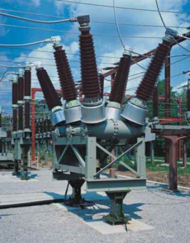
Siemens Dead Tank Circuit Breaker
A quick post in connection with an email question:

Live Tank -  the circuit breaker the switching unit is located in an insulator bushing which is live at line voltage (or some voltage above ground). Live Tank circuit breakers are cheaper than dead tank and require less space.

Dead Tank -  the switching unit is located within a metallic container which is kept a earth potential.  As the incoming/outgoing conductors are taken through insulated bushings, it is possible to place current transformers on these (with a Live Tank arrangement this is not possible and separate CTs are required). 

The terms Live and Dead Tank normally only apply to high voltage circuit breakers


Steven McFadyen's avatar Steven McFadyen

Steven has over twenty five years experience working on some of the largest construction projects. He has a deep technical understanding of electrical engineering and is keen to share this knowledge. About the author

myElectrical Engineering

comments powered by Disqus

  1. tang's avatar tang says:
    8/23/2012 8:15 AM

    What is the ground clearance for dead tank CT?

    • Steven's avatar Steven says:
      8/26/2012 12:17 PM

      With a dead tank circuit breaker, the CT primary side is still isolated, so I'm not sure about why you are worried with ground clearance.


Comments are closed for this post:
  • have a question or need help, please use our Questions Section
  • spotted an error or have additional info that you think should be in this post, feel free to Contact Us


Battery Sizing

This article gives an introduction to IEEE 485 method for the selection and calculation of battery capacity.

Welcome back Bottle

‘Kept looking at a card, y’see? Kept looking at it. Welcome back Bottle. Gods below welcome home. The Crippled God A Tale of the Malazan Book of the...

Microsoft OneNote

A couple of months ago I came Microsoft's OneNote and downloaded the 60 day free trail. Since then I have been using it regularly and now have a full license...

Three Phase Current - Simple Calculation

The calculation of current in a three phase system has been brought up on our site feedback and is a discussion I seem to get involved in every now and...

Differential protection, the good old days

This morning I was explaining how differential protection works to a junior engineer. To give him something to read I opened up the NPAG (Network Protection...

Calculating Cable Fault Ratings

When selecting a cable, the performance of the cable under fault conditions is an important consideration. It is important that calculations be carried...

Cost Performance and Time

Often us engineers get so bogged down in equations, using software, producing drawings and writing specifications that this becomes the sole focus.   ...

How Electrical Circuits Work

If you have no idea how electrical circuits work, or what people mean then they talk about volts and amps, hopefully I can shed a bit light.  I’m intending...

Harmonised Cable Codes and Colours

Within Europe the European Committee for Electrotechnical Standardization (CENELEC) has standardised the both the designation and colour of cables.   ...

Tip – Latitude and Longitude on Large Scale Plans

If you are working on a large plan, get the real coordinates [latitude, longitude] for two or more points and add them to the drawing. That way you can...

Have some knowledge to share

If you have some expert knowledge or experience, why not consider sharing this with our community.  

By writing an electrical note, you will be educating our users and at the same time promoting your expertise within the engineering community.

To get started and understand our policy, you can read our How to Write an Electrical Note