How to Calculate Motor Starting Time
Requests to look at induction motor starting time have come up a few times on the site. Hopefully in this post, I give you guys some idea on how to calculate this. Failing that, hopefully at least some understanding that it is feasible.
Starting Time - it's a little complicated
Later in the article I'll give a formula which you can apply to get an approximate starting time. Prior to that it is worthwhile looking at a few of the influences which make accurate calculation more difficult.
 Motor Torque Speed Curve
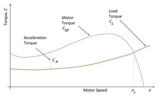
 The first thing to look at is the motor characteristic. The image shows a typical motor torque curve and a hypothetical load torque curve superimposed . The torque available to accelerate the motor up to speed is given by the difference between motor torque and load torque:

Where
Ca - torque to accelerate the motor, N.m
CM – motor torque, N.m
CL – load torque, N.m
As can be seen, as the speed increases both the motor and load torque vary. The motor torque characteristic is also a function of the design and construction of the motor and can vary significantly for motors of the same rating. Starting methods (see Motor Starting - Introduction) also affect the available motor torque and can even affect the shape of the curve.
Any torque used for acceleration, needs to overcome both the inertia of the motor and the load. By using this and knowing and a bit of mechanical engineering (see the reference below), it is possible to derive an equation for the time to accelerate from zero to the running speed:

Where:
ta – time to accelerate to running speed, s
nr – motor running speed, rpm
CM – motor torque, N.m
CL – load torque, N.,
JM – inertia of the motor, kg.m2
JL – inertia of the load, kg.m2
From the above, if you know the motor and load inertias and both the motor and load torque as a function of speed (CM(n), CL(n)) you can calculate the starting time. While it is possible you could do this by solving the equation for an exact solution, in practice you would generally use some numerical solution or piecewise approximation.
With any complexity on the torque curves or starting arrangement, it is obvious that it is not a trivial matter to calculated the time. For larger or particularly important motors, the effort of dealing with this complexity would be justifiable. If required, there are software tools available to assist in the calculation.
Starting Time - an easier [rough] approximation
By introducing some simplifications, it is possible to have an easier to use formulae to give an approximation for the starting time.
The first simplification is to use an average value of motor torque,

Where
CS - the inrush torque, N.m
Cmax - the maximum torque, N.m
Both these figures are available from the manufacturer.
For reduced voltages, torque is reduced by the square of the reduction, so It should be possible to adjust the average torque for reduced voltage starting (i.e. star-delta).
The second simplification is to use an adjustment factor KL to take care of varying load torque CL due to speed changes:
| Type of Load |
| Load Factor, KL |
Lift
|
Fans
|
Piston
Pumps
|
Flywheel
|
|
1
|
0.33
|
0.5
|
0
|
Using the simplifications, the approximate starting time is given by:

Where Cacc is the effective acceleration torque and is given by:

An example will show how this works:
A 90 kW motor is used to drive a fan. From the motor manufacturer and mechanical engineer we have:
- Motor Rated Speed (nr) - 1500 rpm
- Motor Full Load Speed - 1486 rpm
- Motor Inertial (JM) - 1.4 kg.m2
- Motor Rated Torque - 549 Nm
- Motor Inrush Torque (CS) - 1563 Nm
- Motor Maximum Torque (Cmax) - 1679 Nm
- Load Inertia (JL) - 30 kg.m2
- Load Torque (CL) - 620 Nm
- Load Factor (KL) - 0.33


In summary, while the calculation of motor starting time accurately is not trivial, it is possible make realistic estimates for the most common starting scenarios by using a few simplifications. I have also developed a Motor Starting Time Calculator, which you can find under 'Tool's on the menu or use the link here.
If anyone has anything to add, please do so below. It would be particularly interesting if anyone has measured starting times and is able to compare them to those calculated by the above.
References
- Three-phase asynchronous motors
Bibliography: Three-phase asynchronous motors. Generalities and ABB proposals for the coordination of protective devices. ABB, 2008.