Periodic Electrical Installation Inspection – What to Inspect?
 This is the second post in a series of two on periodic electrical inspections. In the first post, I discussed how often inspections should be carried out. If you missed that post, you may want to read it now:
Periodic Electrical Installation Inspection
– How Often?
As with how often, when looking at what to inspect there are two considerations – 1) inspection of systems, which businesses themselves have decided are critical to their operation and 2) the minimum systems which need to be inspected according to regulations.
The aim of any inspection is to ensure that the equipment is still maintaining the safety of persons, protecting equipment and property, providing the correct level of business continuity and has not been damaged or subject to defects.
Regulations such as the IEE Wiring Regulations in the UK and the National Electric code in the US give guidance on the level and detail of the inspection. Regulations tend to deal predominately with the safety of persons and property. Depending on the nature of the installation, it may be prudent for the owner to go beyond regulation by carrying out additional inspections to ensure business continuity.
Inspections will consist of visual investigations, supplemented by testing (for example checking the disconnection of times of protective relays).
- In the UK, IEE Guidance Note 3, Inspection & Testing, lists items which should be considered for inclusion in any inspection and testing routine:
- Inspection – joints, conductors , switchgear, fire barriers, extra low voltage systems, basic protection, protective devices, enclosures, marking and labelling
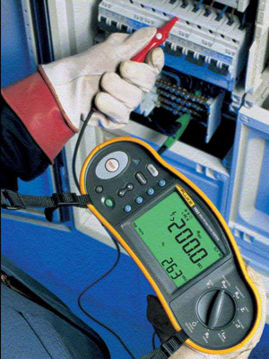
- Testing – protective/bonding/ring-circuit conductor continuity, insulations resistance, polarity, earth electrode resistance, earth fault loop impedance and functional tests (RCD, circuit breakers)
In determining the extent of inspection and testing, considerable care needs to be taken to ensure everything is covered. On large installations, inspection and testing may cover a sample of the system – with subsequent inspections covering different portions of the system.
Inspections and testing will be carried out around live equipment and only suitably qualified personnel should be doing this work. Records and test results should be kept to verify that periodic inspections have been carried. Inspection and testing records can also be compared across time to evaluate changes in systems and aid in planning maintenance.