IEC 61439 - The Switchgear Standard 
By on

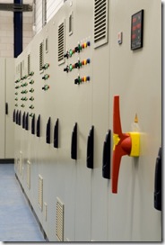
Switchboard_Front
IEC 61439 -
The New Switchgear Standard
The new standard IEC 61439 replaces the old 60439.  Compared to the old standard, the new 61439 is a more clearly defined and takes into account the assembly of pre-tested designs. . 

Some key differences are that the distinction between type tested assemblies (TTA) and partially type tested (PTTA) is gone, verifying the performance is addressed in new ways and the specification of current ratings is updated.  

For more information on testing to the standard, see:

IEC 61439 Verification Methods

Current Ratings

Within the 61439, current ratings are clarified and more clearly defined.t ratings.

  • The standard defines the overall rated current of the assembly (Ina) as the smaller of the sum of  rated currents of incoming circuits or the total current the main busbar is capable of distributing.
  • The rated current of a circuit (Inc) is the rating of a circuit taking in to account the installed devices, disposition and application (and may be lower than the rated current of the devices used).
  • A rated diversity factor (RDF) is assigned by the manufacturer to groups of outgoing circuits which can be simultaneously loaded and takes into account the mutual thermal influence between the circuits.  This can be applied to the whole assembly or a group of circuits.

This clarification of ratings ties the consideration and specification of a switchboard more closely into the manufactured product.  Personally I think is a good thing.  It does put more emphasis on specifiers to understand how the assembly will perform and what they want out of it. 

Typical RDF

The RDF is a figure to be given by manufacturers.  Some typical values I found on the Schneider website are:

Number of main outgoing circuits

Diversity factor

2 and 3

0.9

4 and 5

0.8

6 to 9 inclusive

0.7

10 and more

0.6


Specification of Switchboards

The standard will change how specifiers state their requirements.  Currently specification is often carried out based around devices (i.e. circuit breakers from a particular manufacturer for example), with the device ratings being applied to switchboards.  This is not the case any longer.  There is now a clear need to consider the effect of the enclosure and surrounding components in addition to those of the protective devices and trip units. 

See Also


Steven McFadyen's avatar Steven McFadyen

Steven has over twenty five years experience working on some of the largest construction projects. He has a deep technical understanding of electrical engineering and is keen to share this knowledge. About the author

myElectrical Engineering

comments powered by Disqus


Fault Calculations - Typical Equipment Parameters

A frequent problem in fault calculations is the obtaining of equipment parameters.  While it is always preferable to use the actual parameters of the equipment...

EU Code of Conduct on Data Centres - Best Practices

The European Union is implementing a voluntary code of practice for participants with the aim of improving the overall efficiency of data centres. As part...

Earth Electrode Resistance

Earthing of electrical systems is essential for the correct functioning and the protecting of life and equipment in the event of faults.  The earth electrode...

ABB Technical Guides - Motor Operation

ABB has produced a range of technical guides that offer concise explanations of the major technologies and technical issues in low voltage AC drives. ...

Back to Basics - Ohm’s Law

Electrical engineering has a multitude of laws and theorems. It is fair to say the Ohm's Law is one of the more widely known; it not the most known. Developed...

Low Voltage Switchroom Design Guide

Low voltage (LV) switchrooms are common across all industries and one of the more common spatial requirements which need to be designed into a project...

Maxwell's Equations - Introduction

Maxwell's Equations are a set of fundamental relationships, which govern how electric and magnetic fields interact. The equations explain how these fields...

Low Voltage Fault Tables

The following tables provide quick order of magnitude fault levels for a a range of typical low voltage situations.

Software Usage Guidelines

Using software in our  work is essential for most of us and we are becoming even more dependant on it's use.  While software is a great asset, many times...

How a Digital Substation Works

Traditionally substations have used circuit breakers, current transformers (CT), voltage transformers (VT) and protection relays all wired together using...

Have some knowledge to share

If you have some expert knowledge or experience, why not consider sharing this with our community.  

By writing an electrical note, you will be educating our users and at the same time promoting your expertise within the engineering community.

To get started and understand our policy, you can read our How to Write an Electrical Note