Generation of a Sine Wave
A fundamental concept behind the operation of alternating current systems is that voltage and current waveforms will be sinusoidal – a Sine Wave. This is best explained by considering how a coil of wire behaves when rotated in a magnetic field.
Faraday's Induction Law states that any change in the magnetic environment of a wire will cause a voltage to be "induced" in the wire. This can be expressed mathematically as:

where:
V - induced voltage, V (volts)
B - magnetic flux density, T (tesla)
l - length of conductor, m (metre)
v - velocity between conductor and magnetic field m.s-1 (metre per second)
θ - angle between conductor and magnetic field, radians (or degrees)
If the wire is moved parallel to the magnetic field, the resulting angle is zero and the induced voltage with be zero. If the wire is moved perpendicular to the magnetic field (sin θ = 1) then the maximum voltage will be induced (for a given field and velocity). At any other angle the voltage will be proportional to the sine of the angle.
Generation of Voltage
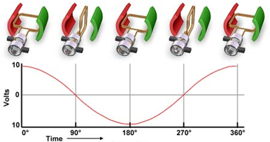
 In practice voltage is generated by rotating a coil of wire through a magnetic field in a generator. The illustration shows this process. Initially the coil is perpendicular to the magnetic field generating maximum voltage. As the coil rotates the voltage decreases according to the sine of the angle until the conductor is parallel to the magnetic field. Further rotation then increases the voltage until once again it is at a maximum (but in the opposite direction).
For each revolution a complete sine wave is generated. The number of sine wave cycles generated per second (the frequency) depends on how quickly the generator is rotating.
In practice each generator coil will have several turns of wire. For 'n' turns, the total voltage will be 'n' times that given by the above equation. Real generator winding are often more complex than that of a single coil, however the basic goal of constructing machines to generate a sine wave still apply.