Voltage Drop in Installations - Concepts
Problems on achieving maximum voltage drop within an installation come up often. Depending where you live, local regulations will have different limits on maximum allowable voltage drop, however the intent of all of these is to ensure sufficient voltage is available at the equipment so that if functions correctly. Specified voltage drops are generally not for an individual cable but for the full installation; from the point of supply connection to the final equipment. Thus the overall voltage drop is a combination of individual voltage drops across multiple cables.
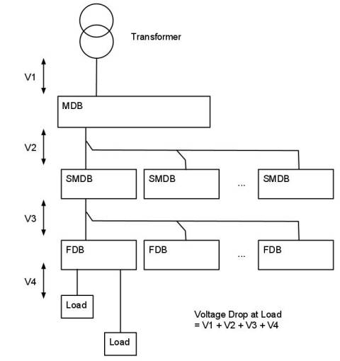
 The figure shows a typical installation. A transformer feeds a main distribution board (MDB), which in turn feeds one or more sub main distribution board (SMDB). Each SMDB feeds one or more final distribution board (FDB), which in turn supplies the connected equipment. It is apparent that the total voltage drop at the final equipment is the sum of following voltage drops:
- Voltage drop (V1) in the cable from the transformer to the MDB (which is carrying the current for all the loads on the system)
- Voltage drop (V2) in the cable from the MDB to the SMDB (which is carrying the current for all loads in all FDB connected to the SMDB)
- Voltage drop (V3) in the cable from the SMDB to the FDB (which is carrying the current for all loads connected to the FDB)
- Voltage drop (V4) in the cable from the FDB to the load (which is carrying the current for the load only)
What becomes obvious is that the voltage drop is a function of the overall system and not trivial to calculate; particularly for a large system. In order to accurately determine the voltage drop to any load, a complete understanding of the system is required. Due to this, design is often carried out using computer software which can quickly evaluate the full system and provide a verifiable solution.
Consideration of a common problem where the voltage drop exceeds the allowable, may help illustrate some of the issues likely to be encountered. Given a voltage drop which is too larger, this could potentially be resolved by increasing the size of the cable from the FDB to the load. Increasing this cable may work or could possibly result in a cable which is too large to be practical. An alternative would be to consider increasing the size of one or more of the cables in the upstream circuits, with the possible benefit of reducing cable sizes on multiple other circuits downstream of this.
Voltage drop and the installation cabling system are integrated and tied together. The example illustrates that consideration of the voltage drop requires a full understanding of the system. Other aspects of the design complicated this further. These include consideration of the cost of the installation, system losses and carbon footprint. By minimizing the amount of copper [cable] used these aspects are reduced, but this needs to be tied in with achieving satiable voltage drops. Attempting to address all these aspects with numerous combinations of different cables and what-if type scenarios can only be realistically addressed by using some sort of computer program.