How to measure power supply quality 
By on

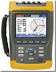
Fluke430PA
Fluke 430 Power Analyser
If your are ever called out to troubleshoot something on your electrical system, one of the first things consider is the supply voltage.  You want to ensure you have a good electrical supply before moving on to other possible problem causes. Here are a few things you can quickly measure to get an impression on the quality of supply:

  • Measure the supply voltage, current and frequency - you want to make sure all these are within expected limits.  If any of the readings are more than 10% out of range, this indicates a problem.
  • Check for phase unbalance - for three phase loads (i.e. motors), the system should be balanced; voltage unbalance of greater than 2% or current unbalance of greater than 6% would potentially indicate a problem.  You can expect some unbalance for single phase loads the phase, however if this is excessive it may still indicate problems.
  • Check for transients - these are more difficult to measure and will need some sort of recording instrument.  Look for transients 50 V and more above nominal.  You should measure for the duration in line with the observed symptoms.
  • Check for voltage dip - look for dips 50 V and more below nominal. Again measure for the duration in line with the observed symptoms.
  • Check the harmonics on the system - total harmonic distortion (THD) of greater than 6% could indicate problems.
  • Check the power factor - this should be inline with expectations.

The above should provide a fair indication that everything is ok with the supply.  If the supply looks good, you can then start investigating potential problems with the equipment itself.

In special cases, the power system parameters are more strictly defined (i.e. the CBEMA Information Technology Curve).  Where applicable, you should be looking to ensure the supply parameters are within the specification.

If you have any additional tips or suggestions on how to ensure the power supply is up to scratch, feel free to add them below.


Steven McFadyen's avatar Steven McFadyen

Steven has over twenty five years experience working on some of the largest construction projects. He has a deep technical understanding of electrical engineering and is keen to share this knowledge. About the author

myElectrical Engineering

comments powered by Disqus


Electromagnetic Compatibility (EMC)

Electromagnetic compatibility (EMC) is the study of coordinating electromagnetic fields give off equipment, with the withstand (compatibility) of other...

Resistors

Resistors are electronic components that oppose the flow of current.  Manufactured in various types and ranges they have a wide application to electronics...

DC Motor Operation

Coils of wire on the rotor carry a d.c. current which generates a magnetic field. A stator magnetic field is created using either permanent magnets or...

Earth Electrode Resistance

Earthing of electrical systems is essential for the correct functioning and the protecting of life and equipment in the event of faults.  The earth electrode...

Fire Resistant and Fire Retardant Cables

Fire resistant and fire retardant cable sheaths are design to resist combustion and limit the propagation of flames. Low smokes cables have a sheath designed...

IEC 61439 Verification Methods

The (relatively new) switchgear and control gear standard, IEC 61439 'Low-voltage switchgear and controlgear assemblies' has three methods which can be...

How to refer fault levels across a transformer

Over the past year or so I've been involved in on going discussions related to referring fault levels from the secondary of a transformer to the primary...

Random Numbers

Using laser optical pulses the random number generator utilizes the time between arrival of random photos to generate the numbers, ensuring true accuracy...

Tips for a better Low Voltage Protection Discrimination Study

Carrying out a protection system discrimination study is critical to ensure the correct functioning of  the electrical system in the event of faults. ...

Difference Between Live and Dead Tank Circuit Breakers

A quick post in connection with an email question: Live Tank - the circuit breaker the switching unit is located in an insulator bushing which is live...

Have some knowledge to share

If you have some expert knowledge or experience, why not consider sharing this with our community.  

By writing an electrical note, you will be educating our users and at the same time promoting your expertise within the engineering community.

To get started and understand our policy, you can read our How to Write an Electrical Note