Capacitor Theory
Capacitors are widely used in electrical engineering for functions such as energy storage, power factor correction, voltage compensation and many others. Capacitance is also inherent in any electrical distribution systems and can play a pivotal role in it's operation.
In order to fully understand capacitors and their use, it is essential that electrical practitioners have a good understanding of capacitor theory.
Capacitance
Symbols Used
C - capacitor, with units of Farad (F)
R - resistor, with units of ohm (Ω)
V - d.c. source voltage in volts (V)
vc - capacitor voltage in volts (V)
I - peak charge or discharge current in amperes (A)
i - instantaneous current in amperes (A)
Q - electric charge (C)
E - electric field strength (V/m)
D - electric flux density (C/m2)
εo - permittivity of free space (f/m) - constant: 8.854 187 817... x 10−12
εr - relative permittivity of dielectric
Capacitors consist of conducting surfaces separated dielectric (insulator). The effect of this is that when a voltage is applied, charge flows into the capacitor and is stored. When an external circuit is connected to the capacitor, this stored charge will flow from the capacitor into the circuit.
Capacitance is a measure of amount of charge which can be stored within a capacitor. The SI unit of capacitance is the farad (F). The farad is the ratio of electrical charge stored by the capacitor to the voltage applied:

The amount of capacitance is defendant on the materials used and geometry of the capacitor.
Formally, capacitance is found by the solution of the Laplace equation ∇2φ = 0, where φ is a constant potential on conductor surface. Simpler geometries can also be solved using other methods (the example shows an example for a parallel plate capacitor).
Example - Parallel Plate Capacitance
_thumb.png)
Parallel Plate Capacitor
(click for larger image) Capacitor shown and assume the dielectric is a vacuum. Electrostatic theory suggests that the ratio of electric flux density to electric field strength is the permittivity of free space:
_thumb.png)
The electric flux density and electric field strength are given by:
With capacitance defined as :

The above equations can be combined and solved to give the capacitance of a parallel plate capacitor (with a free air dielectric) as:
_thumb.png) farad
farad
For more real dielectrics the capacitance will be increased directly in proportion to the the relative permittivity and given by:
_thumb.png) farad
farad
Charging and Discharging of Capacitors
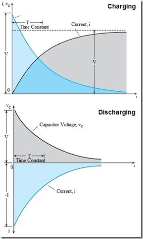
Charging (and discharging) of capacitors follows an exponential law. Consider the circuit which shows a capacitor connected to a d.c. source via a switch. The resistor represents the leakage resistance of the capacitor, resistance of external leads and connections and any deliberately introduced resistance.
_thumb.png)
Capacitor Charging Voltage Capacitor Charging Voltage
When the switch is closed, the initial voltage across the capacitor (C) is zero and the current (i) is given by:
_thumb.png)
- from fundamental capacitor theory
The voltage across the resistor is the current multiplied by its value, giving:
_thumb.png)
From Kirchhoff's voltage law, the d.c. source voltage (V) equals the sum of the capacitor voltage (vc) and voltage across the resistor:
_thumb.png)
Which when rearranged gives:
_thumb.png) and
and _thumb.png)
By integrating both sides, we get:
_thumb.png)
at _thumb.png) ,
, _thumb.png) giving
giving _thumb.png)
By rearranging
_thumb.png) which goes to
which goes to _thumb.png)
and _thumb.png)
The voltage across the capacitor will increase from zero to that of the d.c. source as an exponential function.
Capacitor Charging Current

Capacitor Charging &
Discharging From the above:
_thumb.png)
Giving:
_thumb.png)
Letting the initial current (I), be the d.c source voltage divided by the resistance:
_thumb.png) giving
giving _thumb.png)
Time Constant
The product of resistance and capacitance (RC), has the units of seconds and is refereed to as the circuit time constant (denoted by the Greek letter Tau, τ).
Using this, the equations of voltage and charging current across the capacitor are written as:
_thumb.png)
_thumb.png)
_thumb.png)
Note: increasing the value of resistance R, will increase the time constant resulting in a slower charge (or discharge) of the capacitor.
Capacitor Discharging
When discharging the current behaves the same as that for charging, but in the opposite direction. Voltage across the capacitor will decay exponentially to zero. Equations for both current and voltage discharge can be determined in a similar way to that shown above and are summarized as:
_thumb.png)
_thumb.png)
_thumb.png)
Energy Storage
The greater the capacitance, the more energy it can store.
Current in the capacitor is given by:
_thumb_1.png)
Instantaneous power within the capacitor is the product of current and voltage:
_thumb.png) watts
watts
During an interval dt, the energy supplied is:
_thumb.png) joules
joules
By integrating the instantaneous energy as the capacitor voltage rises, we can find the total energy stored:
_thumb.png) joules
joules
It is worth noting that when connecting capacitors in series, the total capacitance reduces but the voltage rating increases. Connecting in parallel keeps the voltage rating the same, but increases the total capacitance. Either way the total energy storage of any combination is simply the sum of the storage capacity of each individual capacitor.
Resistor Losses
In charging an ideal capacitor there are no losses. However, should a capacitor be charged via a resistor then it should be understood that half of the charging energy will be lost and dissipated as heat across the capacitor.
Consider the above circuit, with a charging current of:
_thumb_1.png)
The instantaneous power loss across the resistor is:
_thumb.png)
Consequentially the total power loss is:
_thumb.png)
Working through the solution gives:
joules
It can be seen that the energy loss is the same as that stored within the capacitor. On discharging, there will also be half the store energy lost within the resistor.
See Also