IEC 61439 Verification Methods
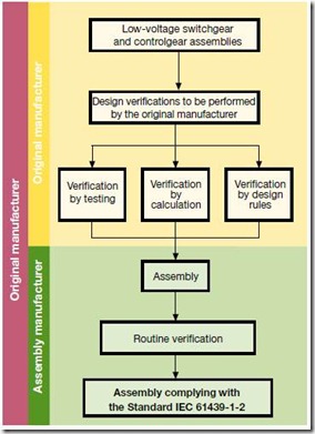
 The (relatively new) switchgear and control gear standard, IEC 61439 'Low-voltage switchgear and controlgear assemblies' , ensures compliance to the standard by a series of design and routine verifications.
Design Verifications
The standard has three methods which can be used to verify the design characteristics of an assembly will meet the standard. These are verification by test, verification by calculation and verification by the use of design rules.
The following table (table D.1 from Annex D of the standard, IEC:2011) summarizes each characteristic and the allowable options for design verification:
| |
|
|
Verification options |
| No. |
Characteristics to be verified |
Clauses or
subclauses |
Testing |
Calculation |
Design
Rules |
| 1 |
Strength of materials and parts:
Resistance to corrosion
Properties of insulating materials:
Thermal stability
Resistance of insulating materials to abnormal
heat and fire due to internal electric effects
Resistance to ultraviolet (UV) radiation
Lifting
Mechanical impact
Marking |
10.2
10.2.2
10.2.3
10.2.3.1
10.2.3.2
10.2.4
10.2.5
10.2.6
10.2.7 |
YES
YES
YES
YES
YES
YES
YES |
NO
NO
NO
NO
NO
NO
NO |
NO
NO
YES
YES
NO
NO
NO |
| 2 |
Degree of protection of the enclosures |
10.3 |
YES |
NO |
YES |
| 3 |
Clearances |
10.4 |
YES |
NO |
NO |
| 4 |
Creepage distances |
10.4 |
YES |
NO |
NO |
| 5 |
Protection against electric shock and integrity
of protective circuits:
Effective continuity between the exposed conductive
parts of the assembly and the protective circuit
Short-circuit withstand strength of the protective
circuit |
10.5
10.5.2
10.5.3 |
YES
YES |
NO
YES |
NO
NO |
| 6 |
Incorporation of switching devices and components |
10.6 |
NO |
NO |
YES |
| 7 |
Internal electrical circuits and connections |
10.7 |
NO |
NO |
YES |
| 8 |
Terminals for external conductors |
10.8 |
NO |
NO |
YES |
| 9 |
Dielectric properties:
Power-frequency withstand voltage
Impulse withstand voltage |
10.9
10.9.2
10.9.3 |
YES
YES |
NO
NO |
NO
YES |
| 10 |
Temperature-rise limits |
10.10 |
YES |
YES |
YES |
| 11 |
Short-circuit withstand strength |
10.11 |
YES |
YES |
NO |
| 12 |
Electromagnetic compatibility (EMC) |
10.12 |
YES |
NO |
YES |
| 13 |
Mechanical operation |
10.13 |
YES |
NO |
NO |
Routine Verification
Routine verification is carried out the detect faults in workmanship and the correct functioning of the panel. The standard (IEC:2011) list the following:
- Construction (see 11.2 to 11.8)
- degree of protection of enclosures
- clearances and creepage distances
- protection against electric shock and integrity of protective circuits
- incorporation of built-in components
- internal electrical circuits and connections
- terminals for external conductors
- mechanical operation
- Performance (see 11.9 to 11.10)
- dielectric properties
- wiring, operational performance and function
Original and Assembly Manufacturer

IEC 61439 Verification, Courtesy ABB The standard also tries to explain the differing roles of the original panel manufacturer and a assembly manufacturer. The original manufacturer is the party who initially carries out the panel design and arranges for the necessary design verifications to be performed. The assembly manufacturer is the party who finally builds the panel to the customers requirements and delivers it. The image shows the relationship between the parties and who performs the verification.
Note: if an assembly manufacturer incorporates his own arrangements, he is then deemed to be the original manufacturer by the standard.
In addition to this post, you may also be interested in my post on 'Forms of Internal Separation' according to the standard:
Switchboard - Forms of Internal Separation