How Electrical Circuits Work
If you have no idea how electrical circuits work, or what people mean then they talk about volts and amps, hopefully I can shed a bit light. I’m intending this post to be a simple introduction to electrical circuits for anyone who doesn’t know, but is interested.
Going to keep the post simple and cover the following:
- Main parts of an electrical circuit (voltage, current and resistance)
- How the main parts are related (the famous Ohm’s law)
- Power in an electrical circuit
- Tying everything together with a few examples
Working with circuits
When talking about electrical circuits there are three main quantities to consider - voltage, current and resistance.
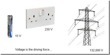
Voltage is the driving force that makes every thing work. To most people, this is probably the most people familiar quantity. The image below illustrates various voltages.

Current is the flow of electricity around a circuit. For example if you connect a lamp to the socket show above, electricity will flow through the wires and be converted into heat and light in the lamp. To have electricity flowing you need some driving force - back to voltage which is the driving force.
Often in trying to explain voltage and current, a water analogy is used. Voltage is the equivalent to water pressure and current the flow of water through pipes.
In any electrical circuit there is resistance to the flow of current. The amount of resistance depends on what is connected in the circuit. The more resistance in the circuit the less current flows. In the lamp circuit, the resistance is the right amount to provide enough current to make the lamp glow - if the resistance was less, the current would be greater and burn out the lamp, if more the current would not be enough to make the lamp glow.
If you can make sense of voltage, current and resistance then you can make sense of how electric circuits work.
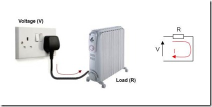
The illustration below shows a heater connected to a socket outlet. Also shown is a schematic representation of the circuit showing the driving voltage, current flow and resistance to the flow of electricity offered by the heater.

If you know the value of two of these parameters, you can always work the value of the third. Around 1825 a scientist named Georg Ohm investigated this relationship and came up with what is famously know as Ohm’s law. In his experiments he found out that in a circuit, the voltage divided by the current was always equal to a constant - the resistance:
 - Ohm’s law; R is the resistance, V the voltage and I the current
The unit used for voltage is the Volt (V), for current is the Ampere (A) and for resistance the Ohm (Ω) named after Georg Ohm.
In addition to the form of equation shown above, Ohm’s law can also be rearranged to find either the voltage or current given the other parameters:

If your still with me so far, then you now have a good basic understanding of how electrical circuits work. To put things into perspective, a couple of examples will help:
Consider the heater circuit shown above. If the voltage of the socket outlet is 230 V and the resistance of the heater 53 Ω (which is typical for a 1 kW heater). Then from the above the current would be 230/53 = 4.4 A (ampere)
As a second example, the resistance of the human body is approximately 1000 Ω. If you accidentally come into contact with a live 230 V conductor, the current flowing through your body would be 230/1000 = 0.23 A
- Safety: any current in the body greater than about 0.05 A can cause serious injury or fatality. With a typical body resistance of 1000 Ω, a voltage as low as 50 V can cause this current to flow. When around any voltage greater that 50 V, you should take as many measures as possible to ensure you don’t come into contact with live conductors.
Something about units
The above examples resulted in currents of 4.4 A and 0.23. When dealing with electrical circuits quantities of voltage, current and resistance can range from in the millions down to small small fractions. This range of numbers from very large or very small can make reading the quantities difficult. To make the numbers easier to read, prefixes are used – two common ones being kilo (k) and mili (m):
- kilo (k) simply means 1000 (one thousand). To convert something to kilo just divide by 1000. For example, 132,000 V can be written as 132 kV (kilo-volts) or 43,000 A as 43 kA.
- mili (m) is sort of the opposite to kilo; it mains 1/1000 (one thousandth) . To convert to mili just multiple by 1000. For example 0.23 A would be 230 mA (mili-amp)
A little on power
Before summarizing what we have gone through so far, the final thing to talk about is power. Reason we have electrical circuits is to do some useful work for us. In a lamp this is to provide light, in a heater to give us heat and in an electrical car to drive us around. Electric circuits move power from the power station to the connected equipment so that we can get this useful work out of them.
Power (P) is measured in watts (w) and if you know the current and resistance of a circuit you can calculate this (you need to trust me on the equation):

So, the power in any piece of equipment is the current squared times it’s resistance - quite simple really. If you want to play around with the math's you can combine this with Ohm’s law to express the in different ways:

An example: consider the heater example above - the resistance is 53 Ω and we calculated the current as 4.4 A. This gives a power of 4.42 x 53 = 1026 w (or approximately 1 kW).
Summary
To summarise, electrical circuits have three interrelated quantities – voltage, current and resistance. Voltage is the driving force that moves the current around a circuit enabling power to be delivered to the equipment. Resistance is provided by any item of equipment to limit the current flow in a circuit. A simple relationship exists between these three parameters and is called Ohm's Law.
Hopefully, the post has helped in giving a better understanding of electricity and electrical circuits. If you any comments, anything or suggestions to improve the post just add below.