What is Aircraft Ground Power
![Image [3] Image [3]](http://myelectrical.com/Portals/0/SunBlogNuke/2/Windows-Live-Writer/What-is-Aircraft-Ground-Power_D132/Image%20%5B3%5D_thumb.jpg)
Pop-up pit for supplying 400 Hz power
(Hong Kong International Airport) Ever wondered what kind of power an aircraft uses when parked at the airport stand.
Normally the aircraft generates it own power, but when parked with the engines switched off power provided by the airport would be connected to the plane.
This connected power is typically 115 V at 400 Hz and is called ground power.
Fixed Ground Power
Fixed ground power is the supply of suitable 400 Hz power using a permanently installed installation for use on parked aircraft.
How Many Ground Power Units (GPU)
For point of use systems, the number of GPU is dependant on aircraft size.
Best practice from an operational and reliability view is one GPU per plug:
- Narrow-Body: 1 x 90 kVA
- Wide-Body: 2 x 90 kVA
- A380: 4 x 90 kVA
Conversion of the mains power to 400 Hz power is typically done either centralised or at the point of use by frequency converters.
In a centralised system, large quantities of power are converted at a central location and then the 400 Hz power is distributed to the aircraft. In point of use, the mains power is taken close to the aircraft, and the frequency conversion carried at it's point of use.
Centralised power systems while cheaper to construct, do have several disadvantages. These include the balancing of the system, maintaining adequate voltage drops amongst others.
Mobile Power
Where fixed ground power is not available, mobile power units can be deployed. These are typically towed or mounted on vehicles and deliver power by utilising diesel generators.
Electrical Characteristics
Aircraft have strict specifications for the quality of power:
115 V ±3 V, 400 Hz
The amount of kVA required is dependant on the aircraft type and size. During design processes, the amount of power required is calculated and suitable equipment installed. For point of use converters (see blow), these are often standardised as 90 kVA units.
Technical Considerations

Unbalanced and Balanced Cables
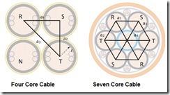
Image Source: LEONI 400 Hz power needs additional technical considerations above that for standard 50 or 60 Hz. Within any cable, the impedance presented by the inductive reactance is proportional to frequency (X = 2πωf). For 400 HZ systems, the impedance will be around eight times larger than normal mains systems and consequently voltage drop becomes a major issue.
In addition for normal four core cables, the distance between the centres of each phase is not equal [due to the neutral conductor taking up space (in the image a3 is larger than a1 or a2)]. This creates an imbalance and consequently the inductance of each phase varies. This variation of inductance between phases, while not that important at mains frequency, become more pronounced at 400 Hz and can lead to imbalanced voltages.
To reduce any imbalance in inductive reactance, often special symmetrical seven core cables are used - with interspersed phases wrapped evenly around a neutral conductor.
Voltage Drop
History of 400 Hz
400 Hz was first chosen for aircraft design as it ensured a more compact design (and hence lighter weight) for the electrical systems.
Generators providing 400 Hz power use less copper in their windings and smaller magnetic cores than those of 50 or 60 Hz - making them lighter.
Given the relative short transmission distances in aircraft, the negative aspects of larger voltage drops at 400 Hz are not so serious. The reduction in weight of equipment more than compensates for this.
Maintaining 115 V at the aircraft plug in connector can be difficult; this is especially so where each phase is unbalanced.
Several methods exist for ensuring the correct voltage level at the aircraft. Two methods which yield reliable results for point of use converters are:
- measurement wires embedded in the main cable measure the voltage at the aircraft. Each individual phase output of the inverter is then adjusted to give the correct voltage at the plane.
- characteristics of the supply system and cable are determined by automatic measurements. The output of each inverter phase is then adjusted according to the measured current.
Frequency Converters
![Image [2] Image [2]](http://myelectrical.com/Portals/0/SunBlogNuke/2/Windows-Live-Writer/What-is-Aircraft-Ground-Power_D132/Image%20%5B2%5D_thumb.jpg)
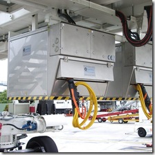
Two 90 kVA point of use frequency converters
(Hong Kong International Airport) Commercial mains power at most airports operates on either 50 or 60 Hz. Frequency converters are required to change this to the 400 Hz required for aircraft operation.
No break power transfer: most modern aircraft operate a no-break power transfer. This means that consumption is transferred from the air-crafts own power generation units to ground generated power without any interruption.
Synchronization and switching over of the power supplies is carried out by equipment on board the aircraft.
Tip: aircraft synchronism equipment is not always the most accurate. Employing frequency converters which can detect aircraft synchronization problems and react accordingly is a good idea.
Final Power Delivery

Bridge Mounted Cable Coiler
Image Source: Cavotec There are many ways for delivering 400 Hz power to the aircraft.
Two common methods employed at larger airports are bridge mounted cable reel devices or apron buried pit systems.
Bridge mounted devices are attached to the passenger embarkation/disembarkation bridges and electrically controlled to dispense the 400 Hz cable. After operations, the device will electrically rewind the cable back onto it's cable reel.
Pit systems typically contain the 400 Hz cable, which is accessed by lifting a lid on the pit. Additionally, some pop-up type pit systems are available, which simply the cable handling. In addition to cable handling, pits systems also need to be designed to take the mechanical load of aircraft driving over them. Being buried, they are also considered to be confined spaces.
Connection to the Aircraft

Standard aircraft
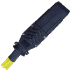
connection plug Connection to the aircraft itself is made using special plug in connectors. Depending on the size of the plane, the number of required connectors varies from one to four.
Aircraft connectors are standardised and rated at IP67.
Connectors are often integrated with push buttons and LEDs for operating frequency converters and power delivery systems. Typical specification ratings would be 200 V, 200 A continuous within a temperature range: -55°C to +125°C.
This note gives a brief introduction to the subject of ground power. If anyone has any questions or comments, please add below.