Three Phase Power Simplified 

By on

A single phase system is perhaps the most common type of system most people are familiar with. This is what people have in their homes and what appliances are plugged in to. For larger amounts of power, three phase systems are used.

Electricity is generated by a coil of wire moving through a magnetic field. The illustration shows three such coils in an electrical generator , spaced evenly apart. Each coil is called a phase and as there are three coils, this is called a three phase system.

ThreePhasePower

From a such a system, power can be supplied as single phase (load connected between a line and neutral) or three phase (load connected between all three lines).   In the illustration, the motor is connected as a three phase load and the socket outlets and lamp as single phase loads.

Terminology

The three winding end connected together at the centre are is called the neutral (denoted as 'N'). The other ends are called the line end (denoted as 'L1', 'L2' and 'L3').

The voltage between two lines (for example 'L1' and 'L2') is called the line to line (or phase to phase) voltage. The voltage across each winding (for example between 'L1' and 'N' is called the line to neutral (or phase voltage).

Voltage Relationship

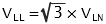
The line to line voltage is the vector sum of the phase to phase voltage across each winding. This is not the same as the arithmetic sum and is given by the following equation:


myElectrical Equation  

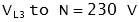
Example:

Line to Line Voltage (VLL)

 myElectrical Equation

myElectrical Equation

myElectrical Equation

Line to Neutral Voltage (VLN)

myElectrical Equation

myElectrical Equation

 myElectrical Equation


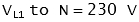
Solving Three Phase Problems

 Tip - to solve a three phase problem, convert it to a single phase problem.

In a balanced three phase system
- each phase delivers/uses 1/3 of the total power
- convert three phase problems to single phase

Resources


Steven McFadyen's avatar Steven McFadyen

Steven has over twenty five years experience working on some of the largest construction projects. He has a deep technical understanding of electrical engineering and is keen to share this knowledge. About the author

myElectrical Engineering

comments powered by Disqus

  1. Jetstar's avatar Jetstar says:
    6/7/2012 3:59 PM

    The 4th line down from TERMINOLOGY reads.

    The voltage across each winding (for example between 'L1' and 'L2' is called the line to neutral (or phase voltage).

    Should it not be (for example between 'L1 and 'N'...)?

    Regads...

    The voltage across each winding (for example between 'L1' and 'L2' is called the line to neutral (or phase voltage).

    • Steven's avatar Steven says:
      6/8/2012 9:03 AM

      Jetstar, thanks for spotting that - your right. I've corrected the error.

  2. Matt's avatar Matt says:
    9/18/2012 5:35 AM

    What about 3 phase unbalanced loads?


Comments are closed for this post:
  • have a question or need help, please use our Questions Section
  • spotted an error or have additional info that you think should be in this post, feel free to Contact Us


The dc resistance of conductors

This is the first of two posts on the resistance of conductors. In the next post I will look at the ac resistance, including skin effect and we deal with...

What does N+1 mean?

The term 'N+1' relates to redundancy and simply means that if you required 'N' items of equipment for something to work, you would have one additional...

Understanding LV Circuit Breaker Fault Ratings

I think this post is going to be helpful to several of our readers. While the IEC low voltage circuit breaker Standard [IEC 60947-2, Low voltage switchgear...

Our internet address and Vanity URLs

Visitors who like to type web address rather then click menus may be interested in how our URL structure works.

IEC 61439 - The Switchgear Standard

The new standard IEC 61439 replaces the old 60439. Compared to the old standard, the new 61439 is a more clearly defined and takes into account the assembly...

Post Authorship

In 2011, with the introduction of it’s Panda search ranking algorithms, Google introduced tools for determining the original author of posts.  The intention...

How to Size Current Transformers

The correct sizing of current transformers is required to ensure satisfactory operation of measuring instruments and protection relays. Several methods...

Cable Sizing Tool

Our cable sizing tool is one of the more popular tools on the site.  The tool enables cables to be sized in compliance with BS 7671 (the IEE Wiring Regulations...

Inductance

When current flows within a wire, a magnetic field is created. The potion of this magnetic field perpendicular to the wire is called the magnetic flux...

Fire Resistant and Fire Retardant Cables

Fire resistant and fire retardant cable sheaths are design to resist combustion and limit the propagation of flames. Low smokes cables have a sheath designed...

Have some knowledge to share

If you have some expert knowledge or experience, why not consider sharing this with our community.  

By writing an electrical note, you will be educating our users and at the same time promoting your expertise within the engineering community.

To get started and understand our policy, you can read our How to Write an Electrical Note