Differential protection, the good old days 
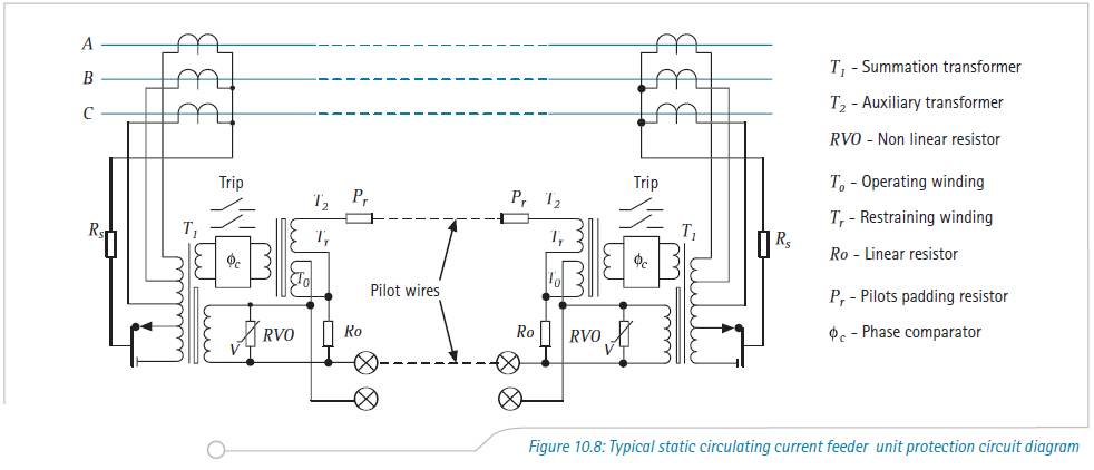
By on


Image reproduced from
'Network Protection and Automation Guide, by Areva
This morning I was explaining how differential protection works to a junior engineer.  To give him something to read I opened up the NPAG (Network Protection and Automation Guide, by Areva) and turned to Chapter 10  ‘Unit Protection of Feeders’.  I was immediately confronted with Marz and Price, circulating current systems, balanced voltage systems, high impedance series connected relays, illustrations like the one shown, etc. ... and remembered my early years.  A time when if you mentioned differential protection to an electrical engineer, they would turn and run in the opposite direction.

Now, I’m not sure if this applies to everyone, but the systems I have been involved with for the past few years have employed numerical relays for differential protection.  Install the two relays, connect together with an optical fibre and gone are all the problems of trying to do this using wires/current between the relays.   I think this is a pretty clear example of how changes in technology have vastly simplified something.  Not only has it simplified the application of differential protection, it also comes with a host of advancements – being able to use CTs manufactured to different specifications as an example.

Numerical relays and optical links may not be the answer to every situation, but I think they make life easier for most of us. 


Steven McFadyen's avatar Steven McFadyen

Steven has over twenty five years experience working on some of the largest construction projects. He has a deep technical understanding of electrical engineering and is keen to share this knowledge. About the author

myElectrical Engineering

comments powered by Disqus


Voltage Drop in Installations - Concepts

Problems on achieving maximum voltage drop within an installation come up often. Depending where you live, local regulations will have different limits...

Motor Starting - Introduction

Motor starting and its associated problems are well-known to many people who have worked on large industrial processes. However, these things are, of course...

Restricted Earth Fault Protection

The windings of many medium and small sized transformers are protected by restricted earth fault (REF) systems. The illustration shows the principal of...

Fault Calculations - Typical Equipment Parameters

A frequent problem in fault calculations is the obtaining of equipment parameters.  While it is always preferable to use the actual parameters of the equipment...

Why a Sine Wave?

I received this question by email a few weeks. First thoughts was that it is a product of the mathematics of rotating a straight conductor in a magnetic...

IEC 61439 - The Switchgear Standard

The new standard IEC 61439 replaces the old 60439. Compared to the old standard, the new 61439 is a more clearly defined and takes into account the assembly...

Cable Trumps

Bored at work and would rather be playing trump card game with you son. The next best thing (or not) maybe the online cable trump card game from AEI Cables...

Questions - Reputation and Privilege

Our question and answer system while letting you do exactly what it says, is much more.  It is a dynamic user driven system, where our users not only ask...

Calculating Cable Fault Ratings

When selecting a cable, the performance of the cable under fault conditions is an important consideration. It is important that calculations be carried...

LED Replacement Light Bulb

The inventor of the first visible light-emitting diode makes history again this year as it begins to show customers a 40-watt replacement GE Energy Smart...

Have some knowledge to share

If you have some expert knowledge or experience, why not consider sharing this with our community.  

By writing an electrical note, you will be educating our users and at the same time promoting your expertise within the engineering community.

To get started and understand our policy, you can read our How to Write an Electrical Note