Introduction to Traction Substations 
By on

Following on from my post on railway electrification voltages, I thought an introduction to traction substations would be a good idea.

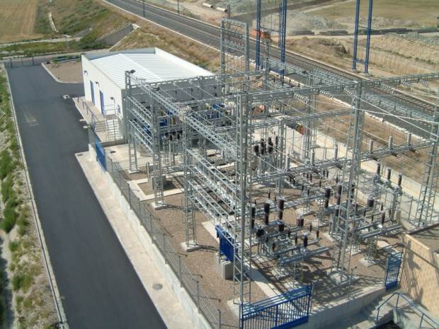
Traction substations are used to convert electrical power as supplied by the power utility (or rail operators own network) to a form suitable for providing power to a rail system (via third rail or overhead line). Depending on the type of rail system this power would be either direct current (dc) or alternating current (ac).

For dc systems, the traction substation core equipment will be the transformers and rectifiers to used to convert the utility supply to dc. Rectifiers are either 6, 12 or 24 pulse. In addition the dc traction substation will contain circuit breakers to ensure the system is adequately protected and switching devices allowing operation and maintenance of the system.

For ac systems, the traction substation core equipment will be transformers which connect to the three phase power utility supply to convert this to a single phase voltage suitable for the rail electrification system being used. Again circuit breakers and switching devices will be provided to ensure adequate system protection and operation and allow for maintenance.

Alternating current supply on the traction side is single phase and can lead to imbalance on the three phase utility beyond allowable limits. Balancing devices (Scott transformers, static convertors, etc.) are often used to achieve these limits.

Generally traction substations will be controlled by SCADA systems and will likely provide power for auxiliary systems such as signaling and other track side purposes.

Traction substations have harsher operational and stability constraints than normal power distribution substations. These include being subject to frequent short circuits, transient spikes, voltage depressions and voltage rises. The use of thyristor controlled traction drives generate significant harmonics, affecting the supply system.

Given the unique issues associated with rail power, the design, construction and operation of traction substations has many technical challenges. Add into this, loading from many trains running at the same time and modern design is heavily dependent on software support.

Please feel free to add comments below or suggest any items which you thing would be a good topic for a more detailed post.


Steven McFadyen's avatar Steven McFadyen

Steven has over twenty five years experience working on some of the largest construction projects. He has a deep technical understanding of electrical engineering and is keen to share this knowledge. About the author

myElectrical Engineering

comments powered by Disqus

  1. Sanjay's avatar Sanjay says:
    1/2/2013 6:08 AM

    Would like to kbnow about the traction substation equipment ararngements,layout,spacing and building foot print of the traction substation.What standards are followed for the traction substations?Is there any specific requirements laid by IEC in this regard?


Comments are closed for this post:
  • have a question or need help, please use our Questions Section
  • spotted an error or have additional info that you think should be in this post, feel free to Contact Us


Copyright Infringement

myElectrical does not support or promote the use of copyrighted material without the copyright owner's consent. If you believe that material for which...

RLC Circuit, Resistor Power Loss - some Modelica experiments

Modelica is an open source (free) software language for modelling complex systems. Having never used it before, I thought I would download a development...

Introduction to Lighting

When looking at the design of a lighting scheme it is useful to have an understanding on the nature of light itself and some of the basic theory associated...

What does N+1 mean?

The term 'N+1' relates to redundancy and simply means that if you required 'N' items of equipment for something to work, you would have one additional...

How to measure power supply quality

If your are ever called out to troubleshoot something on your electrical system, one of the first things consider is the supply voltage. You want to ensure...

Robotics - Home Innovations

We have a sister note to this (Robots - Interesting Video), in which I have posted some videos of interesting robots developed by commercial corporations...

Electromagnetic Fields - Exposure Limits

Exposure to time varying magnetic fields, from power frequencies to the gigahertz range can have harmful consequences.  A lot of research has been conducted...

8 Motor parts and common faults

Straight forward list of some common motor faults.  If I have missed any other common faults, please take a bit of time to add them in as a comment below...

Fault Calculation - Per Unit System

Per unit fault calculations is a method whereby system impedances and quantities are normalised across different voltage levels to a common base.  By removing...

MIT OpenCourseWare

MIT OpenCourseWare, makes the materials used in teaching all MIT subjects available on the Web, free of charge, to any user in the world.

Have some knowledge to share

If you have some expert knowledge or experience, why not consider sharing this with our community.  

By writing an electrical note, you will be educating our users and at the same time promoting your expertise within the engineering community.

To get started and understand our policy, you can read our How to Write an Electrical Note