Network Theory – Introduction and Review
In electrical engineering, Network Theory is the study of how to solve circuit problems. By analyzing circuits, the engineer looks to determine the various voltages can currents with exist within the network.
When looking at solving any circuit, a number of methods and theories exist to assist and simplify the process. This post briefly lists some of the more common network theories. For more detailed analysis of any particular theory you can search the myElectrical site or find more information on one of the many other sources available on the web.
Typically in network theory, we deal with linear and passive elements – most commonly:
- resistors add resistance, R to a circuit. The inverse of resistance (1/R) is the conductance, G.
- capacitors add capacitance, C to a circuit.
- inductors add inductance, L to a circuit.
- reactance, X is a product of having capacitance or inductance in an alternating current (ac) circuit. The inverse of reactance (1/X) is the susceptance, B.
- impedance, Z is the combination of resistance and reactance in an ac circuit. The invers of impedance (1/Z) is the admittance, Y.
- voltage source is a source of voltage within the circuit. An ideal voltage source contains no internal series resistance.
- current source is a source of current within a circuit. An ideal current source contains no internal parallel resistance.
Network Theories
Series and Parallel Circuits
The connecting of elements in series or parallel is probably the most basic type of network. In a series circuit the total resistance (or impedance) is the sum or resistances (or impedances). In a parallel the inverse of the total resistance (or impedance) is the sum of the inverses.
The voltage in a series circuit is the some of voltages across each element, while the current is the same through each element. In a parallel circuit the voltage is the same across each element, whilst the current is inversely proportional to the resistance (or impedance) of each circuit.
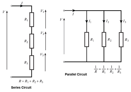
Inductors follow the same law as resistors. That is in series the total inductance is the sum of individual inductances, while in parallel the inverse of the total is the sum of the inverses.
Capacitors are the opposite. In a series circuit the invers of total capacitance is the sum of the inverses for each individual capacitor. For a parallel circuit the total capacitance is the sum of the individual capacitances.
Series and Parallel Circuits – Wikipedia page should you require a more detailed explanation
Ohm's Law
Ohm's Law (developed in 1827 by Georg Ohm), states that the relationship given by the Voltage in a circuit divided by the current is a constant – the resistance (or impedance in ac circuits).

Back to Basics - Ohms Law – myElectrical article explaining Ohm's Law
How Electrical Circuits Work – myElectrical introductory post with some Ohm's Law
Kirchhoff's Laws
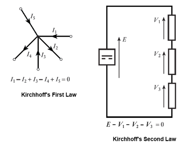
Kirchhoff's Laws comprise of two theorems – the current law and voltage law:
First Law (current) – the sum of currents at a circuit node equals zero
Second Law (voltage) – the sum of voltages around a loop equals zero
Kirchhoff's circuit laws - Wikipedia page should you require a more detailed explanation
Tellegen's Theorem
Tellegen's theorem simply states that the sum of power in all branches of a network is equal to zero, provided at network also complies with Kirchhoff's Laws. For a network with b, branches:

This theorem is still relatively unknown, although it can be applied to a wide variety of problems, can form the basis for proof of most other network theories and applies to any type of element (passive,active, linear and non-linear).
Tellegen's theorem - Wikipedia page should you require a more detailed explanation
Thévenin's Theorem
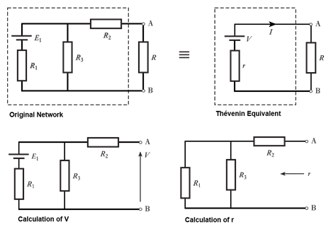
Thévenin's theorem states that any combination of network elements can be represented by a single voltage source and series resistor. The equivalent voltage is calculated by having the branch open circuit; while the resistor is calculated by having any voltage sources short circuited;
Thévenin's theorem - Wikipedia page should you require a more detailed explanation
Norton's Theorem
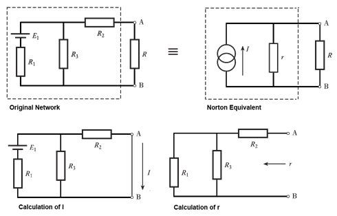
Norton's theorem states that any combination of network elements can be represented by a single current source and parallel resistor. The equivalent current is calculated by having the branch short circuited; while the resistor is calculated by having any voltage sources short circuited;
Norton's theorem - Wikipedia page should you require a more detailed explanation
Source Conversions
A constant voltage source is an ideal voltage in series with a resistor. A constant current source is an ideal current in parallel with a resistor. To convert a voltage source to a current source or (vies-versa):

Note: Norton's theorem could be stated as being Thévenin's theorem but with the equivalent current source
Millman's Theorem
Millman's theorem applies to networks which contain only parallel branches and is used to find the voltage across all the branches. If there are b, branches and each branch contains a resistor R and optional voltage E, than the branch voltage V, is given by:

Millman's Theorem – allaboutcircuits.com worked example on the theory
Star Delta Transforms
Star delta transforms are frequency used to convert between star (or PI) and delta network configurations:
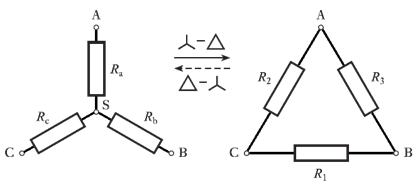
Y-Δ transform - Wikipedia page should you require a more detailed explanation
Nodal Analysis
Nodal analysis is a voltage method which relies on Kirchhoff's first law to produce a set of equations which can then be solved. As a procedural method the steps involved are:
- arbitrarily assign voltage to each node (V1, V2, etc.)
- calculate the current in each branch, for example: node 1 to node 2, resistance R12
gives, I12 = (V1-V2) / R12
- at each node apply Kirchhoff's first law (sum of currents equals zero)
- solve the resulting equations to find the voltages at each node (and hence currents)
Nodal analysis - Wikipedia page should you require a more detailed explanation
Mesh Analysis
Mesh analysis is a current method which relies on Kirchhoff's second law to produce a set of equations which can then be solved. As a procedural method the steps involved are:
- assign a mesh (loop) current to each closed loop in the network
- for each loop apply Kirchhoff's second law (sum of voltages equals zero)
- solve the resulting equations to find the loop currents (and hence network voltages)
Mesh analysis - Wikipedia page should you require a more detailed explanation
Superposition Theorem
If the network contains more than one voltage or current source, superposition allows for a solution to be found by considering each voltage or current source separately and then adding the results. To consider each source separately, all other voltage sources are short circuited and all other current sources are open circuited.
Note: superposition can be particular useful in deriving Thévenin or Norton equivalent networks.
Superposition Theorem - allaboutcircuits.com worked example on the theory
Author's Note:
I've put together the post as more of a summary and included links to other more detailed posts on the site were possible. Where there is not a detailed post on the site, I have included links to articles on external sites so that our readers can still follow up.
While the external sites are good, it would be better if we had some myElectrical written content for the missing network theories. If you're able to put together a post on one of these theorems to help fill this gaps, please do so – it will help greatly.