Photovoltaic (PV) - Utility Power Grid Interface
_thumb.png)
ABB String Inverter (3.3 to 8 kW)
- IEC 61727 Complaint Photovoltaic (PV) systems are typically more efficient when connected in parallel with a main power gird. During periods when the PV system generates energy this can be utilized and the grid energy used at other times.
For large PV systems, any connection interface is likely to need discussion with the power network operator. For smaller systems (around 10 kVA), there are existing standards which will facilitate making a functional and safe grid connection. This note looks at some of the standards.
IEC 61727 Utility Interface
IEC 61727 - Photovoltaic (PV) systems – Characteristics of the utility interface
As an international standard, IEC 61727 specifies the main requirements of a grid interface which will ensure that it is both functional and safe for PV connections of 10 kVA or less. Most the required functionality to comply with the standard is implemented within the PV systems inverter.
When the utility limits move outside normal operational bounds the inventor should disconnect itself from the grid.
Inverter Output Power Quality - the output of any inverter should operate within the following limits:
- the inverter must limit the injection of any d.c. current into the utility to less than 1% of its rated output
- the total harmonic current distortion should be less than 5%
- harmonic current distortion for each individual harmonic should be less than those given in the standard
- the inverter must control flicker to be in line with IEC 61000
- when the inverters output is greater than 50%, the power factor must be greater than 0.9
Note: in most countries there would be local regulations related to connection to an utility power gird. It is incumbent that users wishing to connect to a utility grid understand and adhere to local regulations.
Non-Islanding
If the grid power is lost for any reason then for safety reasons the inverter should stop supplying power. Also if the utility voltage or frequency goes out of limits the inverter should stop supplying power. The maximum disconnection times laid down in the standard to achieve this are:
- V < 0.5 x Vn - 0.1 s
- V ≤ 0.85 x Vn -2.0 s
- V > 1.1 x Vn - 2.0 s
- V ≥= 1.35 x Vn - 0.05 s
- Frequency ±1 Hz - 0.2 s
Vn is the nominal voltage
Once any grid power is restored, the inverter should not connect for some time. This is typically between 20 seconds to 5 minutes and should be agreed with the utility provider.
Local Implementation

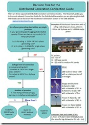
ENA Decision Tree For The
Distributed Generation Connection Guide
Image Source: Energy Networks Association (ENA) Local authorities may have their own guides or standards which need to be applied. These could be in line with IEC 61727 or have a completely different set of connection requirements. Anyone installing a grid connected PV system should follow all local standards.
As an example, the Energy Network Association (ENA) in the UK produces connection guides which are adopted by authorities in the UK. The image (click for a larger version), shows the ENA decision tree for selecting the correct guide.
Installation Requirements
Any PV system will fall under the relevant regulations and standards governing electrical installations.
Within the IEC framework this would be IEC 60364 "Electrical installations of buildings". While any installation needs to fully comply with the standard, part 7-712 deals with particular requirements related to PV systems.
Local regulations will often be in force, for example in the UK, BS 7671 (the IEE Wiring Regulations) is used. If in the US, then NFPA 70 (National Electric Code) would be used.
_thumb.png)
Typical PV Connection Single Line Diagram In designing the PV system and it's grid connection, the designer would typically need to consider the following:
- d.c. protective devices on the PV array output
- a.c. protective devices on the inverter output
- connection of the inverter into the installations main electrical systems
- PV array over voltage protection
- junction boxes for connecting multiple arrays
- devices for isolation of the PV array from the inverter
- devices for isolation of the inverter
- earthing and equipotential bonding of the equipment
Hopefully the note has provided an overview of both utility grid interface requirements and some necessary installation considerations. If you have an comments or would like to discuss, please do so.
See Also