Cable Sizing Tool 

By on

CableSizingFlowChartOur cable sizing tool is one of the more popular tools on the site. The tool enables cables to be sized in compliance with BS 7671 (the IEE Wiring Regulations) and by implication IEC 60364.

This post gives some insight into how the tool works, the calculations carried out and how to use it. With the tool being based on BS 7671, this post will also provide an introduction and explanation of the cable sizing method given in the standard.

The sizing tool can be found at:

myElectrical Cable Sizing Tool

The Procedure

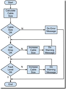
The flowchart (click for a larger image) shows the general procedure followed by the tool:

  • current capacity – a cable size is found which is adequate for the expected current
  • voltage drop – the voltage drop on the selected cable is checked and if to big the cable size is increased
  • fault level – the fault level withstand is checked and if not adequate the cable size is increase

Any errors or warnings generated during the calculation are passed on the the user. 

In addition to cable size the tool also calculates the cable impedance and fault levels at the load end of the cable.

The Formulae

The calculation method follows the procedures given in BS 7671:2008  (the IEE Wiring Regulations), 17th Edition.

Definitions:

Iz - current carrying capacity of the cable (continuous service under defined installation conditions)

It - tabulated value of current (for the type of cable, type of installation, and at an ambient of 30oC)

Ib - design current of the circuit (expected in normal service)

In - nominal setting of any protective device

I2 – operating current of the protective device

Ca - correction factor for the ambient temperature

Cc - correction factor for the type of protective device used

Cg - correction factor for grouping of circuits/cables

Ci - correction factor thermal insulation

Ct - correction factor for the operating temperature of the conductor

Np - number of cables in parallel

tp - maximum permitted operating temperature

Current Capacity

By considering any correction factors, the tabled current for a  cable installed in a given situation can be found.  Once the tabled value of current is found, the cable size is determined by selecting the next largest cross sectional area in the lookup tables.

For single circuits:

image011

For groups where simultaneous overload is possible:
 
image018


For groups not liable to simultaneous overload (the maximum of):
 
image020
 
 
image022
 
 
For cables where overload protection is not required:
 
image026
 

Once It is known, this size of cable is then looked up in the current carrying capacity tables:

  • Tables 4D1A to 4J4A (pages274 to  316) – current carrying capacity

Correction factors are obtained from the following tables (dependant upon cable type and installation):

  • Table 4B1 – rating factors for cables in air, ambient other than 30 °C
  • Table 4B2 – rating factors for buried cables, ambient other than 20 °C
  • Table 4B3 – rating factors for buried cables, thermal resistivities other an 2.5 K.m.W-1
  • Table 4C1 to  4C3 – rating for grouping of circuits/cables
  • Table 52.2 – rating factors for cables surrounded by thermal insulation

Voltage Drop

Voltage drop calculations consider both the power factor of the system and a correction factor for the cable operating standard.  Tables 4D1B to 4J4B of the standard give voltage drops (resistive and reactive) in (mV/A/m), which is equivalent to  mΩ/m (or Ω/m if adjusted).

By looking up in these tables and using the cable length, the sizing tool determines the resistance, R and reactance, X of the cable.  The calculated voltage drop, is then given by:

image038

The temperature correction factor is only applied to the resistance and is given by:

image032

Note: the tool carries out all calculations in complex form.

Fault Levels

The fault withstand rating of the cable is determined using the adiabatic equation:

image035

Where:
S is the cable cross sectional area in mm2
I is the fault current which can flow in A
t is the operating time of the protective device in S
k is a factor related to the conductor material and insulation – tables 54.2 to 54.6 of the standard

Frequently Asked Questions

How does the tool taking into account parallel conductors?

Additional parallel cables are automatically added to group derating (you don't need to increase this manually). 

You can click the ignore checkbox to change this (for example if your cables are more than two diameters apart).: code changes have been made. The updated version of the calculator is now live.

What exactly is the No.Circuits/Cables?

Group derating takes into account heat generated by adjacent cables.  Each circuit is usually supplied by one cable and the number of circuits will equal the number of cables.  Sometimes several cables are run a parallel for a single circuit and this will increase the total number of cables (and group derating).

Tip: if cables are spaced more than twice their overall diameter apart, then no group derating is required.


Steven McFadyen's avatar Steven McFadyen

Steven has over twenty five years experience working on some of the largest construction projects. He has a deep technical understanding of electrical engineering and is keen to share this knowledge. About the author

myElectrical Engineering

comments powered by Disqus

  1. gilly's avatar gilly says:
    7/2/2012 6:15 PM

    The formula for calcualating

    Ct = (230 + Tp - (Ca2 x Cg2 - Ib2/It2)x(Tp - 30))/ (230 + Tp)

    where :
    Ct = Temperature Correction Factor to account for the actual temperature reached with load current flowing taking into account the heating effect of grouping and ambient temperature.
    Tp = Maximum Operating Temperature of the conductor (for PVC = 70 deg C and for XLPE = 90 deg C).
    Ca = Ambient Temperature Correction Factor.
    Cg = Grouping Correction Factor.
    Ib = Design Load Current (in Amps).
    It = Tabulated Continuous Current Carrying Capacity or Current Rating of Conductor at 30 deg C (in Amps).
    30 = The Ambient Temperature (in deg C) the tabulated cable current ratings are designed to.

    I think the above formula for calculating the Operating Temperature Correction Fcator Ct in BS 7671 needs a slight correction for cables installed in underground ducts. For these types of installations the tabulated current carrying capacity is for ambient ground temperatures of 20 deg C, so the Ct factor should be altered to have Tp - 20 instead of Tp - 30. So the formula for cables installed in underground ducts should be as follows :

    Ct = (230 + Tp - (Ca2 x Cg2 - Ib2/It2)x(Tp - 20))/ (230 + Tp)

    Would you aggree ?

    Regards

    Barry

    • Steven's avatar Steven says:
      7/4/2012 7:13 AM

      This is a really good point and I have been looking at the tables and trying to get my head around this.

      To me, the 20oC appears to only apply when looking at the current rating where Ct is not used (Ct is only for voltage drop).

      For the voltage drop tables there is only one figure given for the resistance (regardless if buried our not). I guess this figure is calculated on 30oC and the equation for Ct given in the regulations is correct.

    • gilly's avatar gilly says:
      7/4/2012 9:51 AM

      Thanks for replying Steve
      I only have a copy of the 16th edition of the IEE Regs so maybe it is different in the 17th, but I can't see any reference to 20 deg C only being used when Ct is not used.
      Yes I know Ct is only for volt drop and I am applying this Ct factor to the resistance part of the cable impedance. But in our installations we have two basic types of cable installation :
      1) On perforated cable tray
      2) In duct underground (both in PVC ducts underground and also in larger concrete cable ducts also underground, with lid on the surface)

      So say I'm installing a Copper/PVC cables in both types of installation, i.e. one cable on perforated tray and the other cable in underground duct :

      For Type 1 Cable Tray Installation method E in Table 4D4A & B the current ratings and volt drop values are for an ambient air temperature of 30 deg C
      For Type 2 Cable Duct Installation method D in Table 4D4A & B the current ratings and volt drop values are for an ambient ground temperature of 20 deg C (i.e. if the above ground ambient air temperature is 30 deg C, the ambient temperature in duct below ground would be lower at 20 deg C)

      So I'm figuring that to apply the Ct correction factor to the mV/A/M values derived from Table 4D4B for cable in underground duct then th appearance of 30 deg C in this Ct formula would be meangingless as we don't have 30 deg there to start with, we have 20 deg C and the mv/A/M values are for a conductor temperature of 70 deg C in an ambient temp of 20 deg C, so if the ambient temp in duct changes to a different temperature then Tp - 20 would seem more appropriate than Tp - 30 ??

    • Steven's avatar Steven says:
      7/5/2012 1:13 PM

      Gilly, I still think for the time being I am going to stick with the view that the equation is correct (we may agree to disagree until we get a third opinion).

      I can see where you are coming from with the tp-30 and it may be that this should be tp-20. However, I also think that the 20oC could be taken into account by the Ib2/It2 (where It has been calculated at 20oC). Possibly the tp-30 is because the resistivity used was taken at 30oC. Without knowing the how the equation was derived, it’s a bit of guess work.

      It may be possible to get a better handle on this, by trying to derive a similar equation from basics and see what it looks like. At the moment I don’t have time to look at something like this at the moment, but it’s something I may do in the future.

  2. gilly's avatar gilly says:
    7/4/2012 9:53 AM

    Does anyone know can you email IEE directly with such queries ??
    Thanks
    Barry

  3. Mehrdad's avatar Mehrdad says:
    12/1/2012 2:36 PM

    Dear Steven,

    Regarding to checking the voltage drop at end point, does your Cable Sizing tool consider the network impedance or no?

    For calculating the voltage drop at starting, if we only consider the cable impedance, that means we have considered the "nominal voltage" on the supply bus, while, as you know, during motor starting the voltage on the bus is not "nominal" and will be decreased depending on the network impedance.

    Thanks

    • Steven's avatar Steven says:
      12/2/2012 4:21 AM

      Mehrdad,

      Thanks for the excellent comment and question. Quick answer is that the tool only considers the cable current and cable impedance in determining the voltage drop. It does not consider the source (network) impedance.

      Since receiving your comment, I have given some thought to possibly adding an option within the tool to include the source impedance in the calculation. At the moment I can't see how this would be helpful. On a typical system, many cables are connected to the source. The current (and voltage drop) within the source is dependant on the sum of all the currents in all the connected cables. If we based the calculation of source voltage drop on just a single cable, the results would be wrong. I think this would lead to confusion or problems for many of the tool users.

      To effectively use the sizing tool, you need to have the required voltage drop across the cable under consideration or only be interested in seeing the voltage drop within that cable. For your problem, if you use the sizing tool to calculate the voltage drop across the cable, you would then need to do a seperate calculation to get the voltage drop in the network and add the two together

      Steven

  4. Mehrdad's avatar Mehrdad says:
    12/2/2012 1:43 PM

    Dear Steven,
    Thank you for your quick and clear response.
    In response to your declaration: “If we based the calculation of source voltage drop on just a single cable, the results would be wrong.”

    ,please note that usually at normal operation when all the cables(loads) are connected to source(switchgear), voltage on the switchgear shall be remained around bus nominal voltage by adjusting transformers tap changers.( Our calculations by ETAP show that the voltage on the switchgear bus bars are a bit more than nominal voltage), so we shall not worry about voltage drop on the switchgear bus bars due to all other connected cables to switchgear.
    I think we shall just check the voltage drop on the bus (due to source impedance) only for that single cable.

    For the loads near source we can disregard extra calculation, but for the cases far from the source this may cause the motors can not run successfully at starting.
    The netwrok impedance(including transformers and cable from transformer to switchgear) can be calculated by adding the min short circuit on the bus bar(derived from calculations).

    What is your idea.
    Sorry for my long query.

    • Steven's avatar Steven says:
      12/3/2012 5:00 AM

      Mehrdad

      If your using ETAP, I think you have everything you need to be able to solve your issue. With the cable and motor modules, are you not able fully to analyse your system in ETAP.

      If you don't have the modules, you can use ETAP to get the voltage drop to the busbar supplying the cable and knowing your total allowable voltage drop you have a maximum voltage drop requirement for our cable sizing tool. Alternatively, you can use the network impedance from ETAP, cable impedance from the sizing tool and put together a spreadsheet to do the calculations (normal operation and starting) and see what voltage drops you are coming up with. In this scenario, you can just use the tool to size for current capacity and modify cable sizes based on the spreadsheet voltage drops.

      These are just some suggestions. Hope you are able to find away to solve your problem.

      I do think you have a very interesting assignment and it would be great if you can give us feedback on how you finally resolve this.

      Steven

  5. Mehrdad's avatar Mehrdad says:
    12/3/2012 12:33 PM

    Dear Steven,
    Our ETAP software contains the cable and motor moudule also, but we have an excel based internal software for cable sizing and other electrical activities.
    Before, this software didn’t considered the voltage drop on the bus for cable sizing due to source impedance, but recently we have added an extra module for this case.

    Another question:

    In calculation, Which one you consider for voltage drop calculation: AC resistance or DC resistance of conductors?

    Thank you

    • Steven's avatar Steven says:
      12/10/2012 8:19 AM

      For ac cables the ac resistance is used (for dc the dc resistance).

  6. Notes's avatar Notes says:
    2/1/2013 10:30 AM

    Trackback from Notes

    IEC 60287 "Calculation of the continuous current rating of cables (100% load factor)" is the International Standard which defines the procedures and equations to be used in determining the current carry capacity of cable. The standard is applicable... ...


Comments are closed for this post:
  • have a question or need help, please use our Questions Section
  • spotted an error or have additional info that you think should be in this post, feel free to Contact Us


Back to Basics - Ohm’s Law

Electrical engineering has a multitude of laws and theorems. It is fair to say the Ohm's Law is one of the more widely known; it not the most known. Developed...

Lightning Protection and Earth Electrode Resistance

Most installations involve some form of lightning protection system which is connected to an earth electrode.  The function of the earth electrode is to...

Motor Insulation

Insulation on a motor prevents interconnection of windings and the winding to earth.  When looking at motors, it is important to understand how the insulation...

8 Steps to Low Voltage Power Cable Selection and Sizing

A recurring theme on our forums is cable sizing. Now many installations are unique and require special consideration. However, a lot of the time things...

Star-Delta Motor Starting - Performance

Many questions sent in to the site are in connection with motor starting and in particular star-delta.  For all but the simplest application, there is...

3 Phase Loads

Three phase systems are derived from three separate windings, either connected in delta or star (wye). Each winding can be treated separately, leading...

Dielectric loss in cables

Dielectrics (insulating materials for example) when subjected to a varying electric field, will have some energy loss.   The varying electric field causes...

International System of Units (SI System)

The International System of Units (abbreviated SI) is the world's most widely used system of units.  The system consists of a set of units and prefixes...

Introduction to Lighting

When looking at the design of a lighting scheme it is useful to have an understanding on the nature of light itself and some of the basic theory associated...

Sony Pocket eBook Reader

For the past few years I have reading eBooks on my HTC touch phone. On and off I have debated buying an eReader and recently purchased a Sony PRS-300 ...

Have some knowledge to share

If you have some expert knowledge or experience, why not consider sharing this with our community.  

By writing an electrical note, you will be educating our users and at the same time promoting your expertise within the engineering community.

To get started and understand our policy, you can read our How to Write an Electrical Note