DC Component of Asymmetrical Faults 
By on

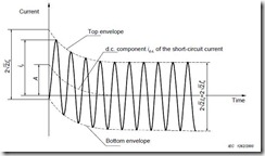
acTypicalFaultThe image (reproduced from IEC 60909) shows a typical fault in an ac system.  From the illustration it can seen that there is an initial dc component (id.c.).  This initial dc component decays over time, eventually reaching zero.  Addition of the dc component to the symmetrical short circuit current gives the asymmetrical fault current.

The initial value of the dc component is dependant on the exact time within a cycle at which the fault takes place and the value of current at that time.

At the initiation of a fault, the current in any system inductance cannot instantly change from it’s value at fault inception to that of it’s steady state fault value.  To compensate for this, a dc component is introduced.  The dc component is equal to the value of the instantaneous ac current at fault inception and of opposite polarity.

Magnitude of the dc component is dependant on where in the cycle the fault inception takes place.  In the worse case, the initial dc offset will be √2 times the symmetrical short circuit value (RMS).

The dc component decays exponentially according to:

10031201

Where:

Ik’’ = symmetrical short circuit current (RMS) (kA)

τ = decay time constant (s)

t = time since fault inception (s)

The time constant τ, is dependant on the system reactance, X and resistance, R and at frequency f is given by:

10031202

Application to Circuit Breakers

Application of the above knowledge to circuit breakers is worth mentioning (we have had a question asked on this recently).  

For most distribution circuit breakers, a system time constant of dc decay  of 45 ms (X/R of 17 at 60Hz) is assumed. Using this assumption, in a distribution application, the dc component is nearly completely decayed after just a few cycles.

Where the system X/R ratio is greater, it will result in a larger time constant, slower decay of the dc component and additional stress on the circuit breaker.  In these instances the circuit breaker needs to be selected accordingly.

As an example, generator circuits typically have a higher X/R ratio and circuit breakers manufactured for this type off application would typically be designed for a system time constant of 133 ms (X/R ratio of 50 at 60 Hz).

The above is a brief introduction to the dc component of asymmetrical fault currents.  If you want to delve into more detail, the IEC 60909 standard “Short-circuit currents in three-phase a.c. systems” is a good starting point.

If you have any immediate questions or comments, please post below.


Steven McFadyen's avatar Steven McFadyen

Steven has over twenty five years experience working on some of the largest construction projects. He has a deep technical understanding of electrical engineering and is keen to share this knowledge. About the author

myElectrical Engineering

comments powered by Disqus

  1. sinnadurai's avatar sinnadurai says:
    1/16/2013 11:16 AM

    How phase sequence disturbance occurs due to asymmetrical faults and what are its effects on system components and connected loads?.

    • Steven's avatar Steven says:
      1/23/2013 8:38 AM

      Difficult question to answer quickly and I’m also not sure what you mean by phase sequence disturbance.

      Asymmetrical faults are by definition unbalanced and will affect each phase differently. Alternatively in a symmetrical fault, all three phases are balanced and each phase is affected equally. I don’t know if this will shed any light on your question. The following post also gives a little more detail, which may help you:

      Fault Calculations - Introduction

      At some stage in the future I do plan to add a few additional posts on fault calculations and will cover this in more depth.

  2. sinnadurai's avatar sinnadurai says:
    1/23/2013 2:32 PM

    Please provide sample current flow paths for +ve,-ve and zero sequence circuits for various kinds of faults(L-G/L-L/L-L-G/L-L-L) series connected involving
    a)generator with solidly/resistance/inductance/peterson coil earthed neutral,
    b)transformers with different vector groups and primary/secondary connections(star/delta) and earth
    c)overhead lines
    d)motors(syn/induction)
    e)capacitor banks/reactors

  3. HS's avatar HS says:
    5/8/2013 3:19 PM

    What is the worst case scenario of DC componenr percentage for 3MVA generator regardless the generator brand name/manufacturer


Comments are closed for this post:
  • have a question or need help, please use our Questions Section
  • spotted an error or have additional info that you think should be in this post, feel free to Contact Us


Always Use PPE

A lot of our members work in countries where PPE (personal protective equipment) is regulated or they work for companies/organizations which take employee...

Occam's Razor

I was reminded of Occam's Razor while reading a book. It's quite a simple principal of logic which has stood the test of time and is accepted as central...

What happened to the cable notes?

If you are wondering what happened to our cable notes, the short answer is that we have moved them to myCableEngineering.com.  The "Knowledge Base" at...

9 power supply issues solved by using a UPS

Installation of a UPS can help in reducing problems due to issues with the power supply.  A lot of people relate this to nine key issues.  Depending on...

Capacitor Theory

Capacitors are widely used in electrical engineering for functions such as energy storage, power factor correction, voltage compensation and many others...

Write your best report

Years ago I was told that you should always try to write the best report you can.  Many years later I still think on this as one of the better pieces of...

How Electrical Circuits Work

If you have no idea how electrical circuits work, or what people mean then they talk about volts and amps, hopefully I can shed a bit light.  I’m intending...

Voltage Drop in Installations - Concepts

Problems on achieving maximum voltage drop within an installation come up often. Depending where you live, local regulations will have different limits...

Voltage Levels – Confused?

I was having a conversation the other day about voltage levels.  While everyone was in agreement that low voltage was 1000 V and less, there was more confusion...

Photovoltaic (PV) - Utility Power Grid Interface

Photovoltaic (PV) systems are typically more efficient when connected in parallel with a main power gird. During periods when the PV system generates energy...

Have some knowledge to share

If you have some expert knowledge or experience, why not consider sharing this with our community.  

By writing an electrical note, you will be educating our users and at the same time promoting your expertise within the engineering community.

To get started and understand our policy, you can read our How to Write an Electrical Note