Variable Frequency Drive

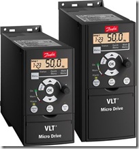
Danfoss Variable Frequency Drives Variable frequency drives are widely used to control the speed of a.c. motors. This note looks at the mechanisms which enable drive units to control the speed. In addition to speed, other advantages offered by variable speed drives are investigated.
Speed Control of AC Motors
General Theory
The speed of an a.c. motor is given by:

Where:
f = frequency, Hz
p = number of pole pairs
S = slip
It is possible to vary the speed of a motor by changing any of the above variables (frequency, pole pairs or slip). However, many of these techniques have some problems associated with them and the most popular method is that of varying frequency.
Frequency Control of Speed
 Pulse Width Modulation
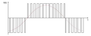
 In frequency control, the variable frequency drive (inverter) supplies a series of dc voltage pulses to the motor terminals at a high frequency (typically 1000 to 10000 Hz). The width of the pulses is varied so that the average voltage seen by the motor is a sine wave (of a given frequency). Changing the width and frequency of the dc pulses varies the frequency of the voltage applied to the motor (and hence the motor speed). This method of frequency control is called pulse width modulation (PWM).
The frequency controller can never give a perfect sinusoidal voltage and hence harmonics will be present. In addition, the motor will generate more noise and high losses.
As the frequency is changed the applied voltage to the motor, is also changed (such that the ratio of voltage to frequency is held constant). This is necessary to provide a constant torque over the operating range.
Circuit Operation
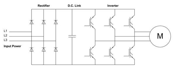
The circuit shows the basic power operation of a variable frequency drive.
 Simple Frequency Drive Power Circuit
 Diodes (or silicon controlled rectifiers, SCR) on the left side form a three phase rectifier whose job is to convert the incoming a.c. supply to a d.c. The arrangement shown is that of a six pulse rectifier. More advance twelve and eighteen pulse rectifiers using phase shifting transformers, which while more expensive can provide a smooth d.c. and generate less harmonics.
The d.c. capacitor acts as an energy store to provide a more constant d.c. voltage to the inverter.
Insulated-gate bipolar transistor (IGBT) on the right side for the inverter and generate the PWM signal. The IGBT act as switches which are turned on by applying a signal to the transistor get connection. By turning on the top IGBT, positive d.c. pulses are generated, whereas the bottom transistors generate negative pulses. Control circuits with the drive control the width of each pulse to generate the PWM signal.
Motor Cooling & Derating
As the PWM waveform is not truly sinusoidal, increase losses will be developed within the motor and will be shown by an increase in the running temperature of the motor. In addition, when the speed of the motor is reduced, the cooling effect will also be reduced and additional external cooling may be required. The characteristics of the motor need to be considering in deciding if there is a need for additional external cooling.
Due to the increase in losses associated with using a variable speed drive and in the absence of specific motor data, as a rule of thumb it is recommended that motor output be derated by 10%.
Note: he higher the switching frequency the closer the output will match that of a sine wave. However, due to increased switching the IGBT will incur more losses.
Variable Speed Drive Units
Feature & Considerations
In addition to basic speed control, modern variable speed drive units have many additional features and benefits. Some of these features are listed below.
-
Acceleration & Deceleration
Drive units allow adjustable acceleration and deceleration rates allowing the speed of motors to be gradually increased or decreased.
Drive units can also monitor the acceleration (by current) and deceleration (by dc bus voltage) and hold the acceleration /deceleration ramp if the motor is about to stall. This can prevent nuisance tripping during the starting of high inertia loads.
-
Motor Protection
Drive units provide full electrical protection for the motor, including over current, over voltage, under voltage, over temperature, and earth leakage.
-
Boost
Normally the output voltage is changed so that the voltage / frequency ratio is kept constant, thereby giving a constant torque. In some situations, it is beneficial to alter this pattern and most modern drive units allow several different patterns to be selected. By altering the voltage frequency ratio, different torque characteristics can be obtained (i.e. higher or lower starting torque, etc.).
-
Braking
Breaking of a motor can be achieved by allowing it to naturally coast to a stop, injecting a dc current or by regenerative breaking (supplying power back into the mains grid or dissipating it across a resistor). Modern drive units can allow all these types of breaking.
Injecting a dc current into the stator of a motor causes the rotating magnetic field to collapse and the rotor to stall. Normally drive units allow both the length of breaking and magnitude of breaking to be controlled by varying the dc current injected. Care should be taken to ensure that both the time and length of braking are set correctly for the connected load.
Regenerative breaking takes the inertia of the load and converts this in the electrical energy, which is fed back into the mains grid (or dissipated across a resistor).
-
Reversing Operation
Variable speed drive units allow the motor to be operated in reverse (without any changing of the phase of the motor supply cables).
-
Maximum & Minimum Frequency
Variable speed units allow the maximum and minimum frequency of use to be set. The means that regardless of setting of the speed control input, the load can always be run under safe conditions.
-
Skip Frequencies
Sometimes resonance occurs within a motor at certain frequencies. Drive units allow bands of skip frequencies to be programmed which will allow the controller to pass quickly through these bands during acceleration and deceleration.
-
Speed Control Input
The speed control input to a variable speed drive unit can take many forms. Most typically this would be a potentiometer on the front of the unit or an external analogue signal (4-20 mA or 0-10V).
Multiple motors on one unit
It is possible to connect multiple motors to one variable frequency drive. This has the advantages of cost saving and a simpler installation. On the other hand all motors will need to be run in an identical operating mode.
If this technique is used, it should be noted that with several motors the variable frequency drive will be unable to detect any overload in an individual motor. Each motor will need it's own overload device.
Galvanic Isolation
Galvanic isolation is applied to the control terminals of the variable speed drive and provides a barrier between these terminals and the rest of the drive. If any of the control inputs or outputs is accidentally earthed, the galvanic isolation should protect the sensitive electronics.
Power Flow and Quadrants

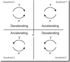
VFD Quadrants Power flow within a variable frequency drive can be defined by four quadrants (see image):
- Quadrant 1 - the motor is rotating clockwise, with the torque the same direction (motor accelerating)
- Quadrant 2 - the motor is rotating clockwise, but the torque in the reverse direction (motor accelerating)
-
Quadrant 3 - motor and torque are rotating in the opposite direction (motor accelerating) -
Quadrant 4 - motor rotating in the opposite direction, with clockwise torque (motor decelerating)
Differing types of equipment will operate in different quadrants, for example pumps typically operate only in quadrant 1, while an electrical car would use all four quadrants.
See Also