Motor Insulation
Insulation on a motor prevents interconnection of windings and the winding to earth. When looking at motors, it is important to understand how the insulation functions and its practical application.
Rating
 Motor Insulation Class
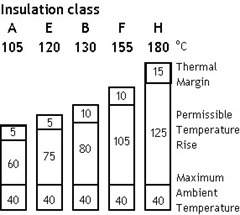
 IEC 60085 ‘Electrical insulation - Thermal evaluation and designation ’ divides insulation into classes. Each class is given a designation that corresponds to the upper temperature limit of the insulating material when used under normal operating conditions.
The correct insulation of the winding of a motor is determined by both the temperature rise in the motor and the temperature of the ambient air.
If a motor is subjected to an ambient temperature higher than 40o C, it must normally be de-rated or a higher insulation class of material used.
Note: motors are typically rated for class 'B' or 'F' insulation
Tip: specify a class ‘F’ insulation, but a class ‘B’ temperature rise. This gives a 25o C margin – can be used for high ambient temperatures for example.
IEC – NEMA Temperature Rise
The table below compares the IEC temperature rise ratings, with the NEMA specification:
Insulation
Class | IEC | NEMA
[1.0 SF] | NEMA
[1.5 SF] |
| A | 60 | 60 | 70 |
| E | 75 | - | - |
| B | 80 | 80 | 90 |
| F | 100 | 105 | 115 |
| H | 125 | 125 | - |
* SF - NEMA Service Factor
Insulation Life and Temperature
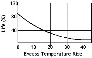
If the upper temperature limit of the insulation material is exceeded the life of the insulation will be reduced at illustrated below.
The selection of insulation class is critical to the life of the motor. A common rule of thumb is that the life of the motor insulation will be halved for every 8 to 10 °C it is operated above the rated insulation temperature
 Motor Life and Temperature
 Testing Insulation
Prior to putting the motor into operations, during routine maintenance and fault finding an insulation tester is used to measure the motor insulation and verify it’s suitability.
Insulation Test Voltages
| Motor Voltage (V) | DC Test Voltage (V) |
| < 2000 | 500 |
| 2001 - 4000 | 1000 * |
| 4001 - 8000 | 2500 * |
| 8001 - 16000 | 5000 * |
Check Resistance First Using 500 V
Recommended Winding Resistance Values
Given a line to line voltage V (kV), winding temperature T (oC) then the minimum insulation resistance (MΩ) of the complete winding should be greater than:

k = 4.159 for a new machine, clean, dry
k = 2.869 for aged machine, clean, uncontaminated
k = 2.771 machine after several years, normal industrial pollution
On a three phase winding the resistance of each phase:

Polarisation Index
 Motor Drying Out Process
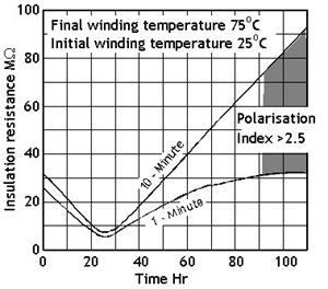
 The polarisation index is the ratio of the winding insulation resistance measured after applying the test voltage for 10 minutes to the value obtained after 1 minute and is used as a guide to the dryness of the winding.

A clean dry winding will typically give a value greater than 1.5. The lower the ratio the greater the leakage path to ground (in effect the capability of the insulation to hold a capacitive charge).
No exact cut-off values exist (1.25 to 2.5 being common). The best guide is a constant ratio over successive readings taken periodically