How to refer fault levels across a transformer 

By on

Over the past year or so I have been involved in on going discussions related to referring fault levels from the secondary of a transformer to the primary side. While this is easy for some people to grasp, for others it's not so straight forward. Here is a brief explanation of how to do this.
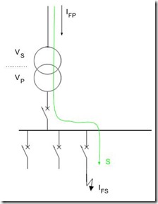
ReferTransformerFaultThe image shows a simple electrical system around a transformer (primary voltage VP, secondary VS).  A fault, IFS (shown on the secondary), will also been seen on the primary side of the transformer IFP.  Because, the voltage level on the primary of the transformer is different than the secondary, the two values of current will be different. 

The value of the primary side fault current is determined by the ratio of the transformer voltages:

image002

That really all there is to it.  If you wanted to refer from the primary to the secondary, just reverse the ratio of the voltages.

Proof of correctness

To verify that the above is true, consider the power (S) transfer from the primary to the secondary of the transformer; shown by the green line.  The power is the flow of energy into the fault and the 'law of conservation of energy' states that the energy entering the system must be the same as that exiting the system.

Ignoring losses (which are small compared to the fault), the power (energy) into the fault must be supplied by via the primary of the transformer and is the same on both sides of the transformer. 

In a single phase system, the electrical power is given by:

image005

applying to both the primary and secondary circuits:

image007

which can be rearranged to give:

image003

For a three phase system (with a symmetrical three phase fault), we have the same result.  The power would be three times that of a single phase system, with voltages as line to neutral.  The three on both sides of the equation cancel, leaving the same answer. 

For three phase systems, unbalanced or earth faults are more problematic.  In these instance it is better to use techniques such as symmetrical components to calculate what is happening.

If you need a little more information on working three phase power from single phase power, you can see:

Any other tips or insights, please add to the comments below.


Steven McFadyen's avatar Steven McFadyen

Steven has over twenty five years experience working on some of the largest construction projects. He has a deep technical understanding of electrical engineering and is keen to share this knowledge. About the author

myElectrical Engineering

comments powered by Disqus

  1. Ella 's avatar Ella says:
    3/6/2013 1:35 PM

    Please assist,

    If I have a Ynd1 transformer and a phase to phase fault exists on the secondary side am I correct to assume that the fault current at the primary side can be represented as a 3 phase fault with a ratio of Vs/2Vp ?

    • Steven's avatar Steven says:
      3/10/2013 9:50 AM

      The above applies to balanced faults. With an unbalanced fault such as yours, the primary currents will also be unbalanced.

  2. Ella's avatar Ella says:
    3/11/2013 12:20 PM

    Thanks for the feedback. Regarding primary currents in unbalanced situations I am trying to understand distribution of fault currents through transformers. If I have a wye grounded - delta transformer with a phase to earth fault on the secondary side, am I correct to assume that the primary fault currents on the wye side will be 0 through each of the lines?

    Furthermore, if the delta side (of the wye groudned delta transformer) is grounded through a zig-zag transformer will the primary currents still be 0?

    Your assistance is much appreciated.

    Thanks
    Ella


Comments are closed for this post:
  • have a question or need help, please use our Questions Section
  • spotted an error or have additional info that you think should be in this post, feel free to Contact Us


Load Flow Study – how they work

A load flow study is the analysis of an electrical network carried out by an electrical engineer. The purpose is to understand how power flows around...

Contribute to myElectrcial

Have an opinion or something to say, want to ask or answer questions, share your knowledge then use our site to do it . As a community of people interested...

3 Phase Loads

Three phase systems are derived from three separate windings, either connected in delta or star (wye). Each winding can be treated separately, leading...

Robots - Interesting Videos

The robot folding towels post below was interesting enough at the time to post a link.  Recently I’ve come across a couple of other interesting videos...

EU Code of Conduct on Data Centres - Best Practices

The European Union is implementing a voluntary code of practice for participants with the aim of improving the overall efficiency of data centres. As part...

IEC Document Designation

Often document control is dictated by project requirements, for example a particular organisation may have an existing numbering system. Existing company...

Wiki Depreciation

We have had the Wiki with us for a long time now, but at last I have decided to say bye bye – more details on why below.

Battery Cars A to Z

Battery powered cars are a hot topic and widely debated. The pros, cons, issues and time frames can be talked about endlessly. An article by the Telegraph...

Multimeter

Multimeters are undoubtedly the most common item of electrical test equipment in use.  Often it is the first piece of equipment people will turn to when...

How D.C. to A.C. Inverters Work

Traditionally generation of electricity has involved rotating machines to produce alternating sinusoidal voltage and current (a.c. systems). With the development...

Have some knowledge to share

If you have some expert knowledge or experience, why not consider sharing this with our community.  

By writing an electrical note, you will be educating our users and at the same time promoting your expertise within the engineering community.

To get started and understand our policy, you can read our How to Write an Electrical Note