Arc Flash Calculations

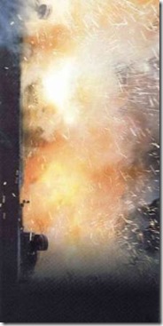
Arc Flash Working in the vicinity of electrical equipment poses an hazard. In addition to electric shock hazard, fault currents passing through air causes Arc Flash.
During arc flash, temperatures of 20,000 oC for several metres around equipment can exist, resulting in severe burn injuries. Quickly expanding air and vaporization of metals causes high pressures, sound and shrapnel leading to multiple types of injuries.
To protect people a risk analysis on the arc flash hazard is carried out to better understand what may occur. Appropriate procedures and personal protective equipment are then employed to minimise potential injuries.
When evaluating arc flash there are two main considerations, 1) the incident energy in the arc flash and 2) flash protection boundary. I will be looking at the calculation of these two parameters in terms of IEE Std. 1584 'IEEE Guide for Performing Arc-Flash Hazard Calculations'.
IEE 1584 Calculation Method
Symbols and their meaning:
V - system voltage (kV)
Ibf - bolted three phase fault current (kA)
Ia - arcing current (kA)
E - incident energy (J/cm2)
EB - incident energy at boundary distance (J/cm2)
En - normalized incident energy (J/cm2)
t - arcing time (s)
D - distance from arc to person (mm)
CB - distance of boundary from arc point (mm)
Arcing Current
In order to determine both the flash protection boundary and incident energy, first the arcing current needs to be calculated.
For system voltages under 1000 V:
Where:
K = -0.153 for open configurations and -0.097 for box configurations
For system voltages above 1000 V:
The arcing current is then given by:
Incident Energy
To calculated the incident energy, first normalized incident energy is calculated. The result of this calculation is the incident energy for a arc duration to 0.2 s and at a distance from the arc point to the person of 610 mm. Once the normalized energy has been calculated, this is then adjusted to reflect the actual arcing time and distance.
The normalized incident energy is given by:
Where:
K1 = -0.792 for open configurations and -0.555 for boxed configurations
K2 = 0 for ungrounded or high resistance ground systems and -0.113 for grounded systems
G = the conductor gap (see table below)
The incident energy is then given by:
- voltages ≤ 15 kV and gaps ≤ 152 mm
Where:
Cf = 1.0 for voltages greater than 1000 V and 1.5 for voltages less than 1000 V
x = is a distance exponent from the table below
- voltages > 15 kV or gaps > 152mm
Note: for voltages greater than 15 kV, it is not necessary to first calculate En
Note: to convert J/cm2 to cal/cm2 multiply by 0.239
| Gap and distance factors |
Voltage (kV) |
Equipment Type | Typical gap between
conductors (mm) | Distance factor,
x |
0.208 - 1
| Open Air | 10-40 | 2.000 |
| Switchgear | 32 | 1.473 |
| MCC and Panels | 25 | 1.641 |
| Cable | 13 | 2.000 |
| >1 - 5 | Open Air | 102 | 2.000 |
| Switchgear | 13-102 | 0.973 |
| Cables | 13 | 2.000 |
| >5 -15 | Open Air | 13-153 | 2.000 |
| Switchgear | 153 | 0.973 |
| Cables | 13 | 2.000 |
Flash Protection Boundary
The flash boundary is the distance from the arc point to a location when the incident energy is less than a given value. Knowing the incident energy, the flash boundary distance is given by:
- voltages ≤ 15 kV and gaps ≤ 152 mm
- voltages > 15 kV or gaps > 152 mm
Where:
Cf = 1.0 for voltages greater than 1000 V and 1.0 for voltages less than 1000 V
x = is a distance exponent from the table above
EB can be set at 5.0 J/cm2 for bare skin or at the rating of any proposed PPE. The limit of 5.0 J/cm2 is that at which a person is likely to receive second degree burns.
Summary
To carry out arc flash calculations, first workout the arcing current, then the incident energy and finally the arc flash boundary. Pretty straight forward.
To make life a little easier I have created a calculator to do the grunt work. You can find it here:
Arc Flash Calculator
It anyone has an comments or spots any errors in the above, please chip in below.