Tip – Latitude and Longitude on Large Scale Plans 

By on

If you are working on a large plan, get the real coordinates [latitude, longitude] for two or more points and add them to the drawing.  That way you can always work out the scale and dimensions.

I know that drawings have scales, grids etc. on them and they are supposed to work.  However, many times I've come across drawings where things don’t tie up.  There can be hundreds of reasons – mix-ups as drawings are moved between different parties, human errors in CAD, messed units,  printing problems, etc.  Having just spent a few hours sorting out the latest wrongly scaled drawing that’s come across my desk, I thought it would be helpful to pass on this tip.

As a bit more general information, we have the following:

Understanding:  latitude are parallel lines running North and South of the equator. Longitude are vertical lines running West or East from the Greenwich prime meridian (located just outside London).  Distance between lines of latitude are approximately equal (minor variances due to the shape of the earth.  Between lines of longitude the distance is greatest at equation and the lines converge at the poles.

Presentation: latitude and longitude can be presented in degrees, minutes, seconds or decimal degrees.  To mark coordinates using degrees, minutes, seconds - it is generally accepted that the latitude should be written first followed by longitude.  The latitude degrees should be two digits and the longitude three digits (i.e. 08°14’16” 128°34’32”).  Designations N, S, W or E are not required, although often used.

Accuracy: when using on site plots, make sure you have sufficient accuracy in the coordinates (this will usually mean two or more decimal places on the seconds).  One second of latitude is approximate equal to 30 M.  One second of longitude is approximately equal to 30 M at the equation, moving to zero at the poles.

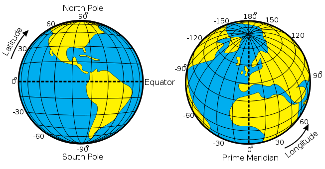
Image reproduced from Wikipedia (http://en.wikipedia.org/wiki/File:Latitude_and_Longitude_of_the_Earth.svg),
access 04 October 2011


Steven McFadyen's avatar Steven McFadyen

Steven has over twenty five years experience working on some of the largest construction projects. He has a deep technical understanding of electrical engineering and is keen to share this knowledge. About the author

myElectrical Engineering

comments powered by Disqus


Dielectric loss in cables

Dielectrics (insulating materials for example) when subjected to a varying electric field, will have some energy loss.   The varying electric field causes...

Introduction to Current Transformers

Current transformers (CTs) are used to convert high level currents to a smaller more reasonable level for use as inputs to protection relays and metering...

Railway Electrification Voltages

This post is quick introduction and overview to different railway electrification voltages used in answer to a question sent in via email. While there...

Gas Insulated or Air Insulated Switchgear

Various arguments exist around SF6 Gas Insulated (GIS) and Air Insulated (AIS) medium voltage switchgear. Recently we had to change a GIS design to AI...

Surface Treatment – Ladders, Trays and Baskets

Steel ladders, trays and baskets form the backbone of cable containment systems. Often these items need some form of surface treatment to prevent corrosion...

Electric Motors

Collection of links to various places with useful motor information. I’ll try and return to the page every now and again to update it with any motor notes...

Battery Sizing

This article gives an introduction to IEEE 485 method for the selection and calculation of battery capacity.

Post Editing Tips

If you at all familiar with programs like office and outlook, then adding and editing posts is pretty straightforward and intuitive.  However, there are...

IEC 61439 Verification Methods

The (relatively new) switchgear and control gear standard, IEC 61439 'Low-voltage switchgear and controlgear assemblies' has three methods which can be...

Why a Sine Wave?

I received this question by email a few weeks. First thoughts was that it is a product of the mathematics of rotating a straight conductor in a magnetic...

Have some knowledge to share

If you have some expert knowledge or experience, why not consider sharing this with our community.  

By writing an electrical note, you will be educating our users and at the same time promoting your expertise within the engineering community.

To get started and understand our policy, you can read our How to Write an Electrical Note